DSO RTU
Telecontrol cabinet version 4 (TCKv4)
Fluvius telecontrole with the telecontrol cabinet version 4 (TCKv4) over IEC 60870-5-104.
Older Fluvius files still use the telecontrol cabinet version 4 (TCKv4) instead of Netflex. The grid study tells you: it mentions "telecontrolekast versie 4". The Voltmasters EMS follows the Fluvius specification TAU341K01.
Difference with Netflex
- One P setpoint for the assets together, no limits at the connection point and no consumption steering.
- A Q setpoint as a target, not a band.
- Both setpoints are a percentage of the installed power Pinst.
- Fluvius measures in the cabinet itself. The EMS sends no measurements back.
- The cabinet disconnects the installation itself. No IO module is needed for the emergency stop.
The connection
Same as Netflex: IEC 60870-5-104, the EMS is the server on TCP 2404, common address 100, through an ethernet-to-USB adapter on the controller. See RTU connection.
Configuration
Go to Configuration → Grid & market → DSO RTU settings.
- Set the telecontrol provider to Fluvius TCKv4.
- Enter the installed power Pinst (kW) as Fluvius registered it. Left empty, the installed power of the asset group is used.
- In the table below, tick the devices in the registered asset group. Only those devices are steered.
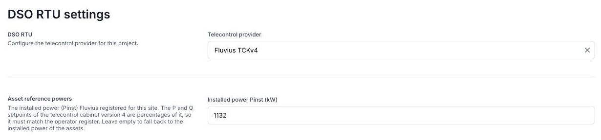
If Fluvius TCKv4 is not in the list, update the controller first.
What Fluvius sends
| Function | What the EMS does |
|---|---|
| P setpoint | Upper limit on the production of the asset group, in % of Pinst. Negative is production: -40 % allows 40 % of Pinst, -100 % imposes nothing. |
| Q setpoint | Target for the reactive power, in % of Pinst, positive is inductive. Applies only in Q mode remote. Split between battery and PV by their installed power. |
| Q mode | Local or remote. In local mode the local reactive operating point applies. |
| Test | Test mode during commissioning. |
| Disconnect status | The cabinet has disconnected the installation. The EMS sets PV and battery to 0 kW and restarts from 0 once reconnected. |
What the EMS reports back
A mirror of the Q mode, the test mode, the P setpoint and the Q setpoint as soon as they arrive. The EMS sends no measurements: Fluvius measures P, Q and U at the connection point and P and Q per production unit itself.
Emergency stop
The decoupling switch and its position signals are wired straight to the cabinet, not to the controller. The cabinet opens the switch itself and reports it through the disconnect status.
Local reactive operating point
In local Q mode the grid study imposes a reactive operating point: while the site injects, 5 or 10 % of the injected power inductive, and possibly 32 % at high grid voltage. Set it under Configuration → Grid & market → Grid settings → Reactive operating point:
- Inductive share of the injected power: 5 or 10 %, as in the study.
- Second operating point at high voltage (Uc): the supply voltage from the study. Empty when the study states no second operating point.
The EMS regulates the reactive power at the connection point with the battery and the PV. A remote Q setpoint always takes precedence.
Commissioning
- Ask Fluvius for Pinst. It is not always the power in the study.
- Check that the connection is active and that Fluvius runs a general interrogation and a clock sync.
- Fluvius tests in test mode: P setpoint, Q setpoint in both modes and the disconnect.