Microgrid
How Microgrid works
The operating modes of a Voltmasters microgrid and how the controller moves between the grid, the battery island, the generator and back.
The controller decides on its own, about once per second, which mode the site is in. This page explains the modes and what happens at every transition. The thresholds named here are set in the microgrid settings; the values between brackets are the defaults.
A complete outage in seven steps. Watch who forms the grid: blue for the grid, green for the battery, pink for the generator.
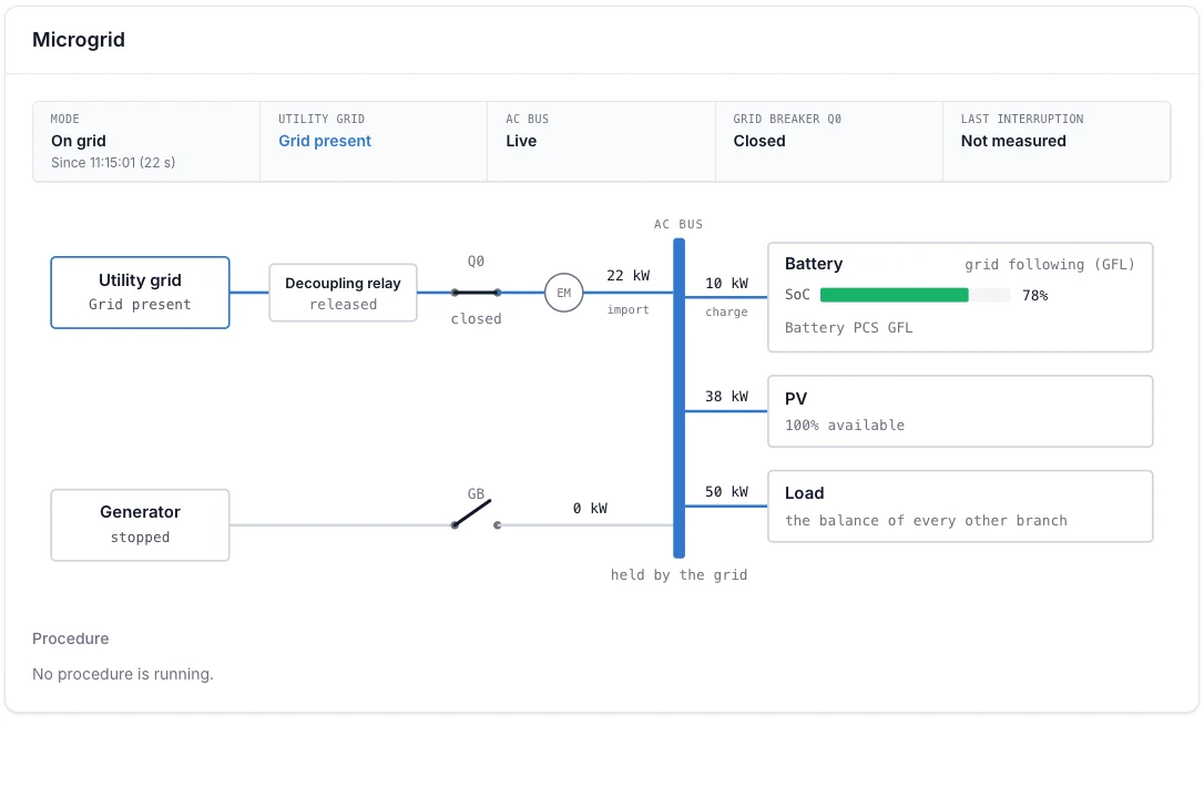
On the grid: the battery stands ready
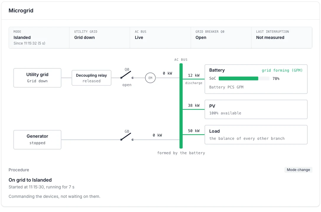
The grid fails: the battery forms the island
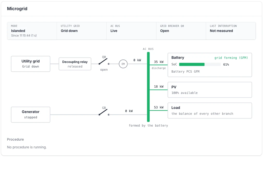
Island operation on the battery
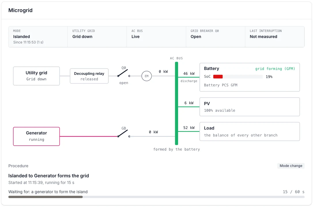
Battery low: the generator starts
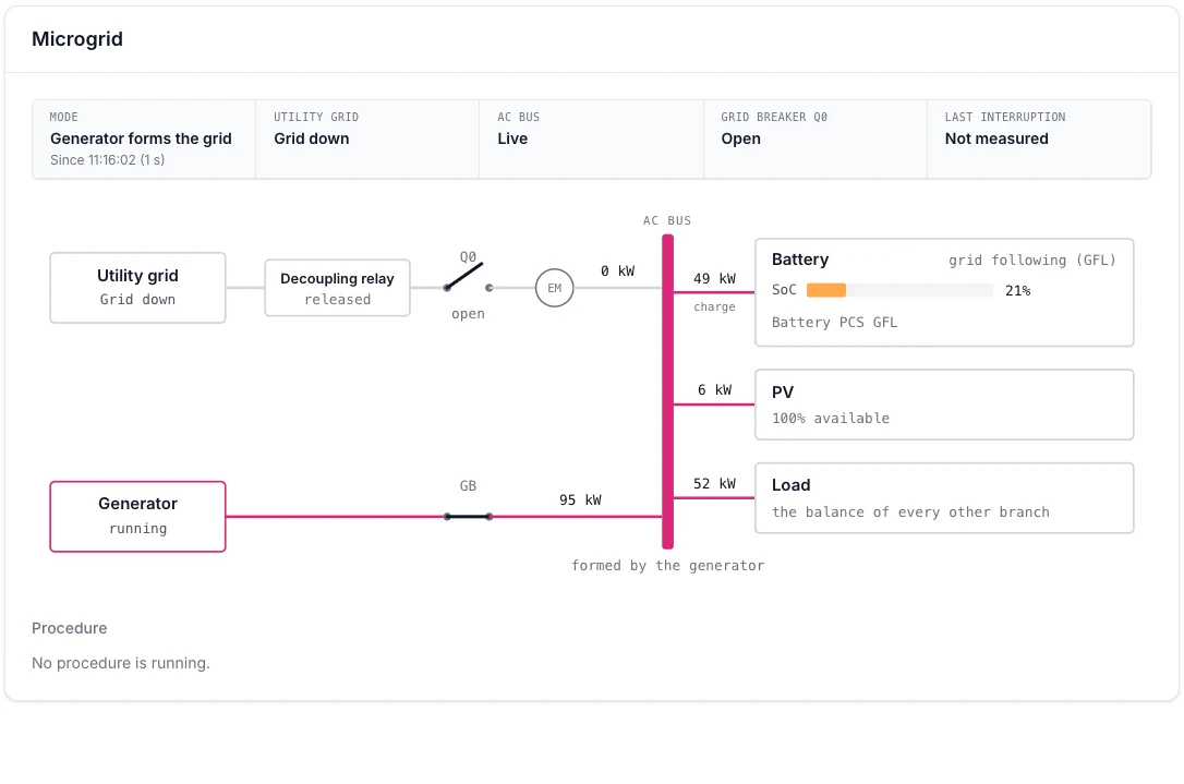
The generator forms the grid and charges the battery
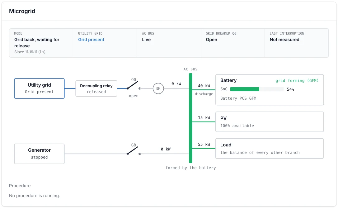
The grid is back: waiting for release
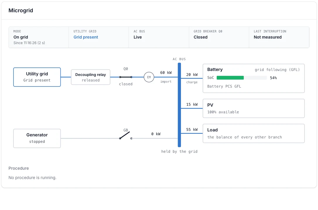
Reconnected: back on the grid
Operating modes
| Mode | What it means |
|---|---|
| On grid | The site is connected to the public grid. The battery follows the grid and runs the normal control strategy. |
| On grid with generator | On the grid, with the generator supporting the site. Only when generator support with the grid present is allowed. |
| Grid fault, still coupled | The grid is outside its window, but the site is not yet separated from it. |
| Islanded | The site is separated from the grid and the battery forms the grid. |
| Islanded with generator | Island operation, with the generator supporting the battery. |
| Generator forms the grid | The generator forms the grid; the battery follows and charges. |
| Grid back, waiting for release | The grid is stable again, the site still runs as an island until the reconnection is released. |
| Returning to the grid | The reconnection procedure is running. |
| Switching between modes | A transition between two modes is in progress. |
| Fault | The microgrid logic stopped in a fault and no longer switches modes on its own. An incident is raised. |
On the grid
- The controller watches the grid voltage and frequency. The grid counts as usable inside the grid window (207 to 253 V, 49.5 to 50.5 Hz).
- The battery keeps an island reserve (50 %): on the grid it does not discharge below this state of charge, so energy is ready for an outage. Only holding the grid import limit may use the reserve. The controller tops it up from the grid at any price. Set it to 0 to turn it off.
From the grid to island operation
When the grid leaves its window, the controller opens the grid breaker and switches the battery inverter to grid forming. The site then has its own grid. With the EMS performing the transfer, the switchover costs a short interruption.
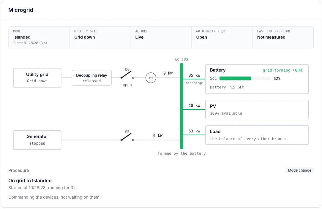
The switch to island operation: Q0 is open, the battery forms the AC bus and the procedure panel shows the mode change.
In island operation
- Power reserve (10 %): the controller keeps this share of the available power free to absorb a sudden load.
- Load shedding: below the load shedding SOC (30 %), the controller starts shedding loads in the order of the load shedding priorities. Critical loads are never shed.
- PV: by default the PV inverters stay online with a limited setpoint, so they never produce more than the site and the battery can absorb. Alternatively the PV is disconnected from the AC bus. See PV while islanded.
The generator takes over
The battery reaches the start threshold
Below the generator start SOC (20 %), the controller starts the generator. The battery keeps forming the grid while the generator runs up.
The generator forms the grid
Once the generator is ready, it forms the grid and the battery switches to grid following. The generator powers the site and charges the battery. The procedure panel shows what the controller waits for.
The battery reaches the stop threshold
Above the generator stop SOC (90 %), the controller stops the generator again, after its minimum runtime, and the battery takes over.
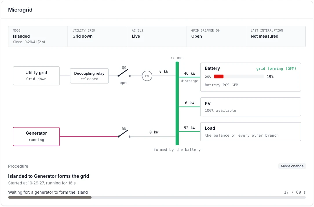
The battery is at 19 %: the generator runs, its breaker GB is still open, and the controller waits for it to form the island.
By default the generator only runs in island operation. With Generator support with the grid present it may also support the site on the grid, for example to shave a peak.
The grid returns
When the grid stays inside its window for the grid stable time (60 s), the site enters Grid back, waiting for release. In manual mode a user releases the reconnection; in automatic mode the controller reconnects after a delay. The procedure is described in Grid reconnection.
The grid transfer is performed by the EMS: the controller runs the whole sequence itself. A static transfer switch that takes over the transfer in hardware is not supported by the controller yet.