Voltmasters Platform
Device settings
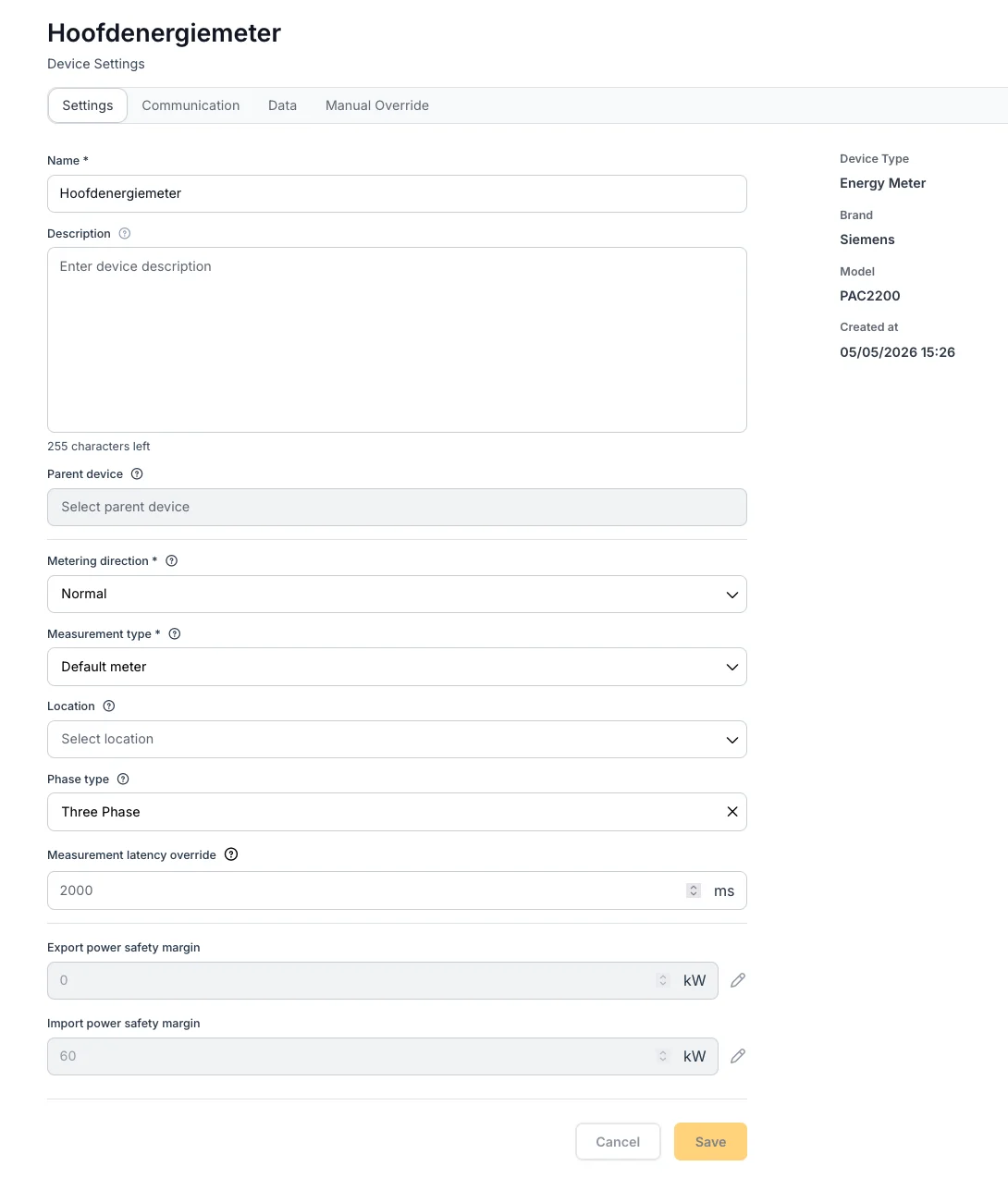
The configuration tabs of a device in the Voltmasters EMS: Settings, Communication with the Modbus details, and Data with live parameter values.
Opening a device reveals several configuration tabs:
- Settings: edit basic properties such as name, description, location, and measurement type.
- Communication: configure the protocol, for example Modbus TCP/IP, plus the IP address, port, and slave ID used by the device to communicate with the platform.
- Data: view a table of real-time parameters and their current values, such as power, consumption, voltage, and currents. Each row shows the parameter name, current value, and timestamp.
- Load Manager: enable load management for this meter and set the maximum power that may pass through it. See Load management below.
- Manual Override: create manual overrides for controllable modules. Specify the module, override value in kW, and time period. Current and previous overrides are listed below.
- Actions: device-specific commands, such as restarting a battery system remotely. See Device actions below.
These features allow fine-grained control over each meter, PV string, battery, or inverter.
Voltmasters EMS: device settings
Communication settings
Besides the protocol, IP address, port and slave ID, two settings on the Communication tab determine how the controller deals with the connection itself.
Exclusive or shared TCP connection
Some devices accept only one Modbus TCP connection at a time, others accept several. Per device you can therefore choose whether the connection must be exclusive, so the controller keeps the socket for itself, or may be shared with other clients.
- Choose exclusive for devices that break down or drop the controller when a second client connects.
- Choose shared when another system (a monitoring portal, a service laptop, a second EMS client) has to reach the same device at the same time.
Fallback on communication loss
For PV inverters and EV chargers, the EMS applies a fallback power limit when it loses communication with the device: the last setpoint sent stays in force on many devices, so the limit that applies during a communication failure has to be a deliberate choice. That limit is configurable per device.
- Set it low (or to zero) when an uncontrolled asset would violate an export limit or a grid-operator constraint.
- Set it high (full power) when losing production or charging power is worse than briefly running unlimited.
The fallback is released again as soon as communication is restored.
The fallback limit is a safety net, not a control setting. Choose it together with your installer, in line with the grid-connection limits of the site and any DSO RTU obligations.
Device actions
The Actions tab of a device lists the commands the EMS can send to that specific device. Which commands are available depends on the brand and model.
- Restart: supported battery systems can be restarted remotely, without a site visit. Use this when the system is unresponsive or after a fault that requires a restart.
A restart interrupts the operation of the device: the battery stops charging or discharging until the system is back online, and control resumes only once the device reports itself as available again. Do not restart during a period in which the installation must stay controllable, for example during an active telecontrol constraint.
Load management
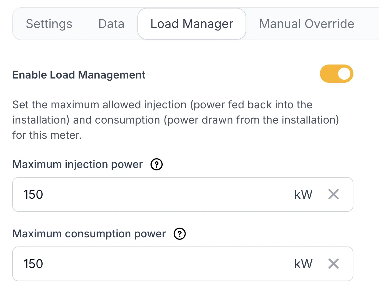
Load management keeps the power flowing through an energy meter below a limit you set. It is configured per meter, on the meter's Load Manager tab:
| Setting | Description |
|---|---|
| Enable Load Management | Switches load management on for this meter. |
| Maximum injection power (kW) | The maximum power that may be fed back into the installation through this meter. |
| Maximum consumption power (kW) | The maximum power that may be drawn from the installation through this meter. |
Limits across the whole metering hierarchy
Load management is not limited to the main meter. Every meter in the installation can carry its own limits, and the EMS enforces them all at the same time:
- the main meter protects the grid connection itself;
- a sub-meter protects what sits behind it (a transformer, a distribution board, a cable or a single building), even when the grid connection as a whole still has room.
Each meter is kept below its own limit, so a busy sub-circuit is throttled without slowing down the rest of the site.
Unevenly loaded phases: per-phase protection
The limits are set in kW for the connection as a whole, but on a three-phase connection the fuses and the connection rating are per phase. When the phases are loaded unevenly, the total can be well below the limit while one phase is already over its share, and it is that single phase that trips the main breaker.
When the meter measures its power per phase, the EMS therefore protects each individual phase as well. It does so pessimistically: every limit check treats the site as if all three phases carried the same load as the heaviest one.
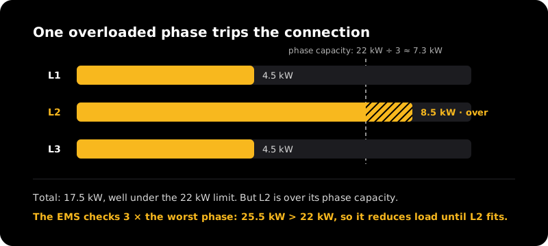
Pessimistic three-phase limiting: the total looks safe, but one phase is overloaded, so the EMS acts as if all three phases were as heavily loaded as the worst one.
What the EMS does when a limit is approached
When the power measured by a meter approaches its limit, the EMS intervenes in a fixed order, from the least disruptive measure to the most:
- The battery: charging is reduced or stopped and, if needed, the battery discharges to take load off the meter.
- EV charging: the charging power of the EV chargers behind that meter is curtailed.
- Controllable loads: on/off loads are shed, lowest priority first.
Only when the earlier steps cannot free up enough power does the EMS move to the next one, so equipment is switched off as a last resort.
The order in which assets are used is the project-wide load shedding priority list under Configuration → Strategy → Load shedding priorities. The same list is used for grid-limit protection and for a Fluvius Fall-Back Flex activation, so the behaviour is identical whatever triggers the reduction.
To keep the grid import of the whole site under its limit, use the import limit and the peak shaving reserve in the project settings. Load management on a meter is the same idea, applied one level deeper in the installation.
Manual override
This manual describes how to manually charge or discharge the battery using a manual override in the EMS system.
During a manual override, the algorithm no longer controls the battery automatically. The system only follows the configured setpoint.
Navigate to Devices
- Log in to the EMS portal.
- Click Devices in the left navigation menu.
Open the device settings
- You will see an overview of all devices.
- Find the desired device in the list.
- Click the gear icon to the right of the device to open the device settings.
Open Manual Override
- You are now on the Device Settings page.
- Click the Manual Override tab at the top of the page.
Configure the override
Fill in the following fields:
- Controllable module: select the module you want to control, for example charge or discharge power.
- Override value (kW): enter the desired power level:
- Use a negative value, for example
-20 kW, to discharge the battery. - Use a positive value, for example
+20 kW, to charge the battery.
- Use a negative value, for example
- Period: set the from and till moment of the override. Because both moments are pickers, an override can also be scheduled in advance: it starts by itself at the from moment and ends at the till moment.
Click Create Override to save and activate the setting.
Which modules you can override depends on the device. For battery systems (PCS) that support it, reactive power can be overridden in the same way as active power, within the reactive-power limits configured in the project settings.
Monitor and stop the override
- Under Current Overrides, you can see the active override with its date, module, type, value, and period.
- To end the override early, click Stop next to the relevant override.
- Previous overrides appear in the Previous Overrides section at the bottom of the page.
When setting the override value, always take into account the applicable import and export limits of your connection. Never set a value that exceeds the permitted import or export limit, to avoid grid overload or violations of your network operator's requirements.
Once the configured period has elapsed, the algorithm automatically resumes control of the battery.