DSO RTU
Commissioning and certification
How Voltmasters validates the DSO RTU link during commissioning, how the grid operator's certification runs, and how to follow every value the operator sends on the DSO RTU dashboard while the test is under way.
A DSO RTU installation is only complete once the link has been validated and certified. Voltmasters validates the operation at commissioning and assists remotely during the grid operator's official inspection, the certification or conformity test. This page describes both, and how to follow the test on the platform.
What Voltmasters validates at commissioning
When the installation is put into service, Voltmasters verifies the complete chain, not just that the link is up:
- The RTU connection: the grid operator's RTU reaches the controller and the link is stable. See RTU connection.
- Data exchange: every command and measurement data point is present and correctly mapped.
- Active-power limits: injection and consumption are actually capped to the commanded values, at the connection point and per asset group.
- Reactive-power control: the local and remote Q modes and the Q band behave as specified.
- Emergency stops: both the software stop and, where installed, the hardware stop through the IO module.
- Feedback and measurements: the EMS mirrors the right state and reports the right measurement channels.
Validation is done against real measurements: we confirm that the installation's injection and consumption follow each command, not just that the command was received.
Prepare the configuration
Most certifications that fail do so on configuration, not on behaviour: a reference power that does not match the operator's register, a PV reported in a channel it is not registered in, an emergency stop without a physical relay. Work through the operator's configuration page before the test date. For Fluvius that is Configuring Fluvius telecontrole, which ends in a checklist.
Before certification can take place, make sure:
- [ ] The RTU is installed and the network link to the controller is in place.
- [ ] The configuration matches the operator's documents: study document, zone sheet, single line diagram and register values.
- [ ] All assets the operator may steer are added, verified and controllable in the EMS.
- [ ] The hardware emergency stop is installed, wired and configured, with the IO module's watchdog and safe state set.
- [ ] A certification date is agreed with the grid operator and shared with Voltmasters, so remote assistance can be planned.
How the certification runs
The grid operator performs the certification on site with its own RTU and its test bench. For Fluvius the inspector works through a fixed sequence, each step with the test reason code (99):
- Communication: the link is up, the general interrogation returns every data point, alarms reach the operator's SCADA.
- Emergency stops: the stop for consumption and the stop for production, including the feedback of the measurement channels while the stop is active.
- Connection point setpoints (
MAXSETP,MINSETP): the site's import or injection has to follow the percentage at the grid meter. - Asset setpoints (
MAXSETAP,MINSETAP), when technical flex applies: the registered assets, as a group, have to follow the percentage at the virtual asset coupling point. - Reactive power (
MINSETQ,MAXSETQ): the measured Q at the connection point has to enter the band.
Commands with the test reason are handled exactly like normal commands; the reason only marks them as part of the inspection. Voltmasters follows the test remotely, watches the same values the inspector watches, and resolves issues in real time wherever possible.
Following the values on the DSO RTU dashboard
Every command the RTU sends lands on the DSO RTU page of the project (Monitoring → DSO RTU) within a few seconds. During a test, keep that page open next to the inspector's bench.
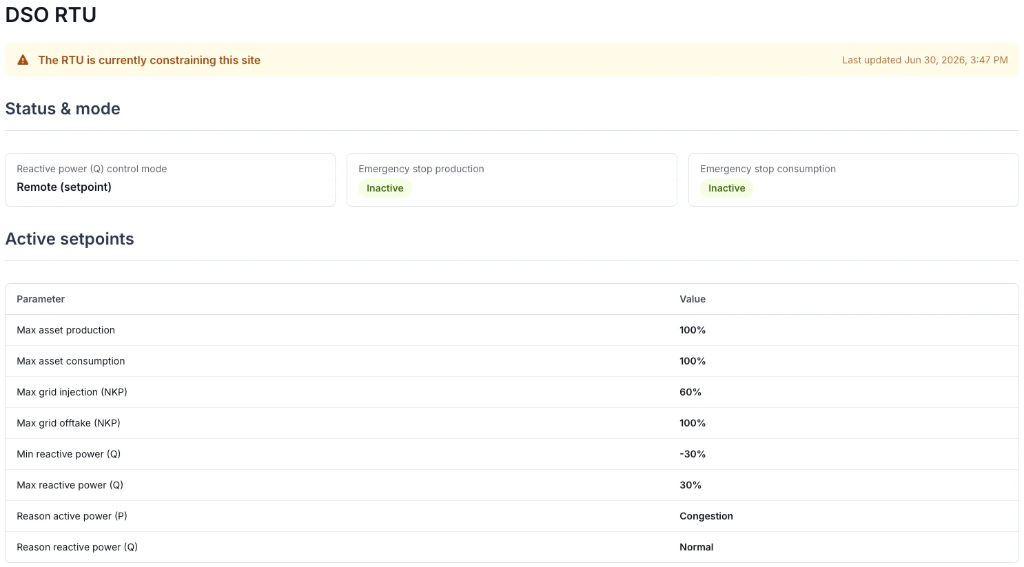
The live snapshot: the banner says whether the RTU is constraining the site, and the table lists every setpoint in force.
The snapshot at the top shows the state as the controller last reported it:
- The banner turns orange when a setpoint is below 100 % or the reason is not normal, red when an emergency stop is active, and green when nothing constrains the site. Its timestamp tells you how fresh the snapshot is.
- Status & mode shows the Q control mode and both emergency stop states. During the emergency stop test the relevant tile must read Active while the inspector holds the stop, and go back to Inactive when it is released.
- Active setpoints lists every percentage in force, with the reason codes. A 100 % means no limitation. During the test the reason reads Test.
The RTU history below it lists every change the RTU sent, and a heartbeat row at fixed intervals while nothing changes. Switch the filter to Changes only to see just the inspector's commands, or Restrictions only to see when the site was constrained. The date range defaults to the last seven days and can span at most 31 days. Per row you see the emergency stop state, the maximum production and consumption in force, any per-type setpoints, and the Q mode.
Read the two together: the history tells you what arrived and when, the snapshot tells you what is in force now.
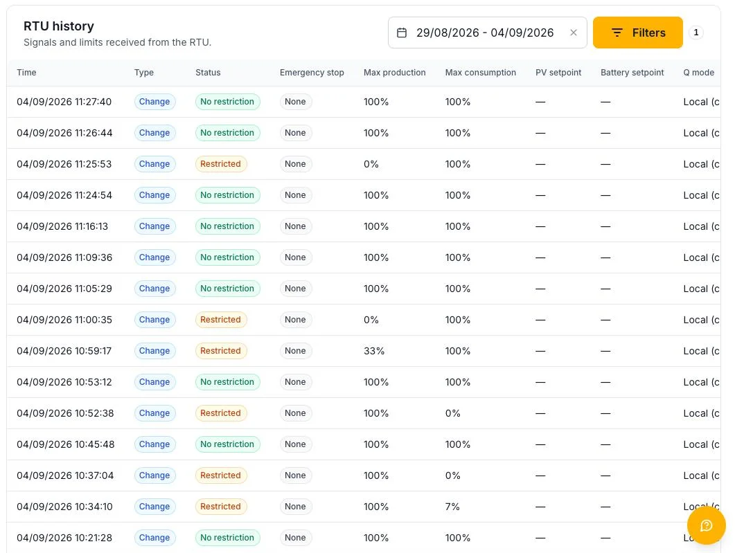
The RTU history of a Fluvius certification, filtered on changes only: the inspector sends MAXSETAP 7 % and 0 %, releases them, then MINSETAP 33 % and 0 %. Every row is one command as it arrived.
What to check per test step
| Step | What the dashboard must show | What the installation must do |
|---|---|---|
| Emergency stop | The stop tile Active, a red banner, a history row with the stop | Battery to 0 kW and, for the production stop, PV to 0 kW within seconds; the relay output opens the coupling. On release the assets resume. |
MAXSETP, MINSETP |
The percentage under Max grid offtake (NKP) or Max grid injection (NKP) | The grid meter settles at or below the percentage of the contractual access power. Compute the expected kW before the step: percentage times the access power under Grid settings. |
MAXSETAP, MINSETAP |
The percentage under Max installation consumption or Max installation production | The registered assets, summed, stay at or below the percentage of the reference power. PV in the group nets against battery charging; PV outside the group plays no part. See the asset setpoint checklist. |
MINSETQ, MAXSETQ |
The Q mode Remote (Q band) and the band under Min / Max reactive power (Q) | The measured Q at the connection point moves into the band; the EMS commands only the difference, not the band edge. |
The dashboard shows percentages; the inspector talks in kilowatts. Compute the expected kilowatts before each step from the base of that setpoint: the access powers for the connection point setpoints, the reference powers for the asset setpoints. How the RTU setpoints are processed has the formula and a worked example per law.
When the numbers do not match
- Nothing arrives on the dashboard: the RTU is not connected to the controller, or the controller has not reported yet. Check the incidents for telecontrol not reachable and the RTU connection.
- The percentage arrives but the installation does not move: the asset is unmanaged, or its integration does not accept the setpoint. The controller raises a warning for a registered asset it cannot steer.
- The installation moves, but to a different value than the inspector expects: the two sides use a different base. Compare the reference powers and the access powers with the inspector's figures, and check which devices the inspector counts at the virtual asset coupling point.
- The exact kilowatts per law: the controller debugger shows, under TelecontrolConstraintController, every percentage with its reference power and the resulting kilowatts, and for the Q band the measured and the commanded reactive power. Voltmasters reads it during the test.
After certification
Once the grid operator approves the certification, the installation is cleared for normal DSO RTU operation. From that point:
- DSO RTU runs continuously and autonomously.
- The link and the installation's compliance are monitored; a lost connection or a command that cannot be executed is surfaced as an incident.
- Configuration changes (limits, added or removed assets, emergency stop wiring) must be revalidated and, if the grid operator requires it, re-certified. Fluvius asks to be told about every change of the installation.