Device integrations
ABB
Supported devices: Terra AC charger, Terra Gateway Pro
Our EMS supports integration with EV chargers from ABB. ABB provides a broad range of AC and DC charging solutions for residential, commercial, and public charging.
The charger communicates with our EMS for monitoring and smart charging control.
Supported devices
- Terra AC charger: a single AC charging station, controlled directly by our EMS.
- Terra Gateway Pro: a site controller that sits in front of a group of ABB DC chargers. Our EMS controls the site as a whole through the gateway rather than each charger individually.
Terra AC charger
Configuration
After the electrical installation of a charger is complete, follow these steps to configure the charger:
- Download the configuration app from ABB
- On the dashboard, select "Configure a charger."
- Enable Bluetooth on your phone, as this is necessary for the app to communicate with the charger during the commissioning process.
- Choose a charger from the available list.
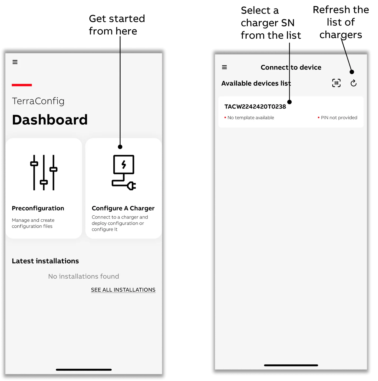
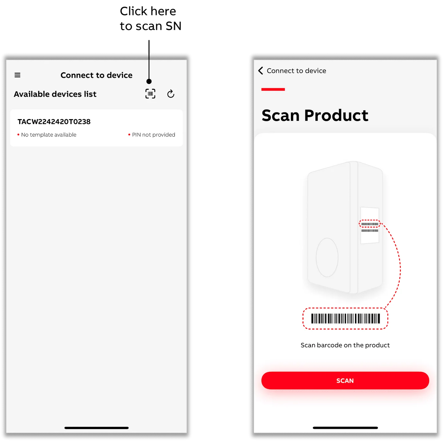
- You can also select a charger by scanning the SN barcode with the app.
- Be sure to scan the charger's SN bar code, which usually begins with "TAC" (although this may vary depending on the product variant).
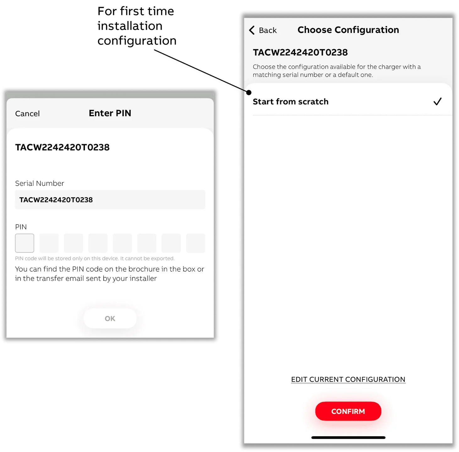
- After selecting a charger to connect to, enter the PIN.
- Select below the option "EDIT CURRENT CONFIGURATION" - or if the charging station has not yet been configured, then select "Start from scratch."
- Make sure your phone or mobile app is connected to the Internet for PIN validation.
- Throughout the process, the app will display a pop-up confirming that all settings will be applied to the charger simultaneously once you get to the last step.
- Click on the "Energy management" submenu.
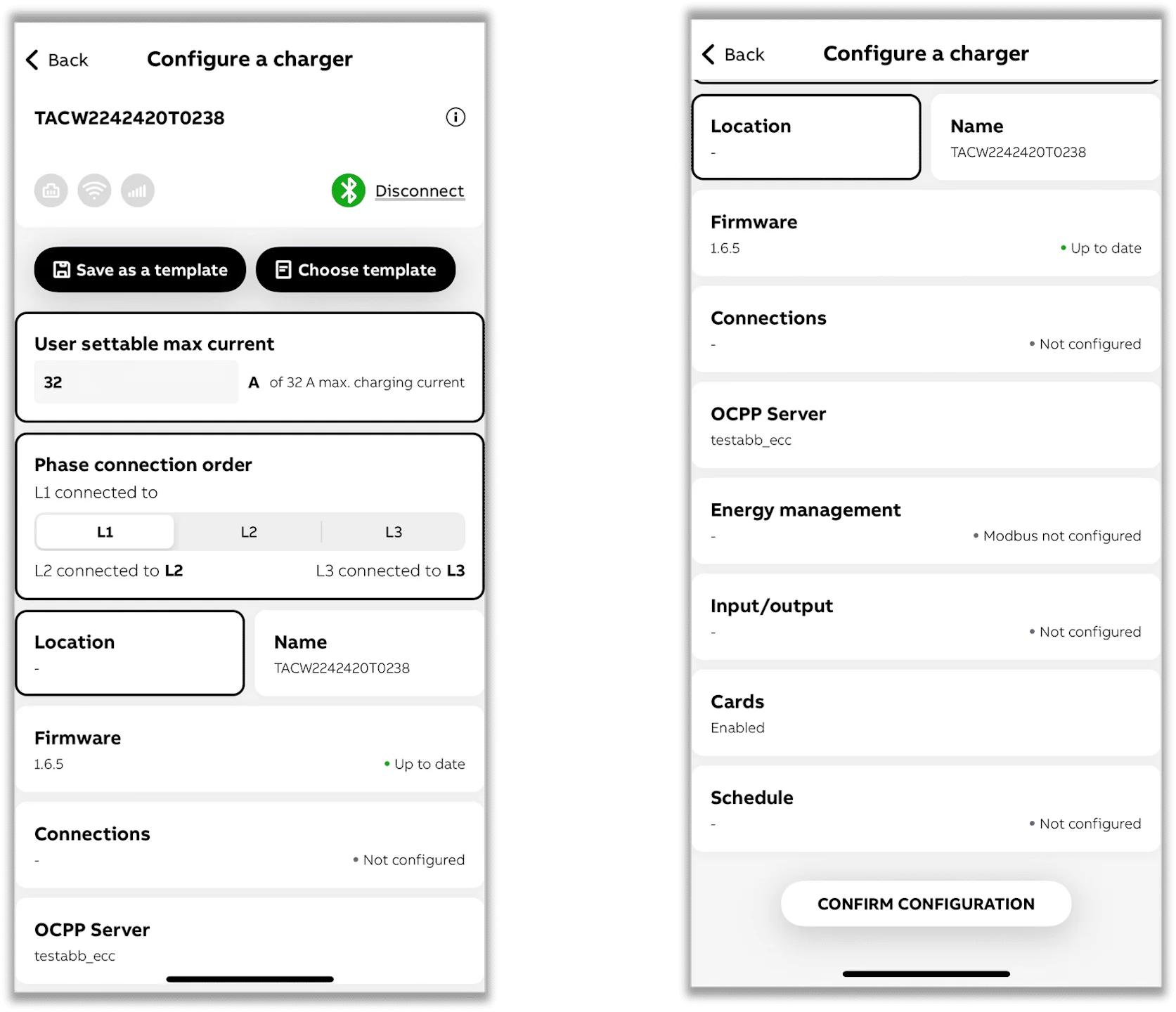
- Toggle "Modbus" on.
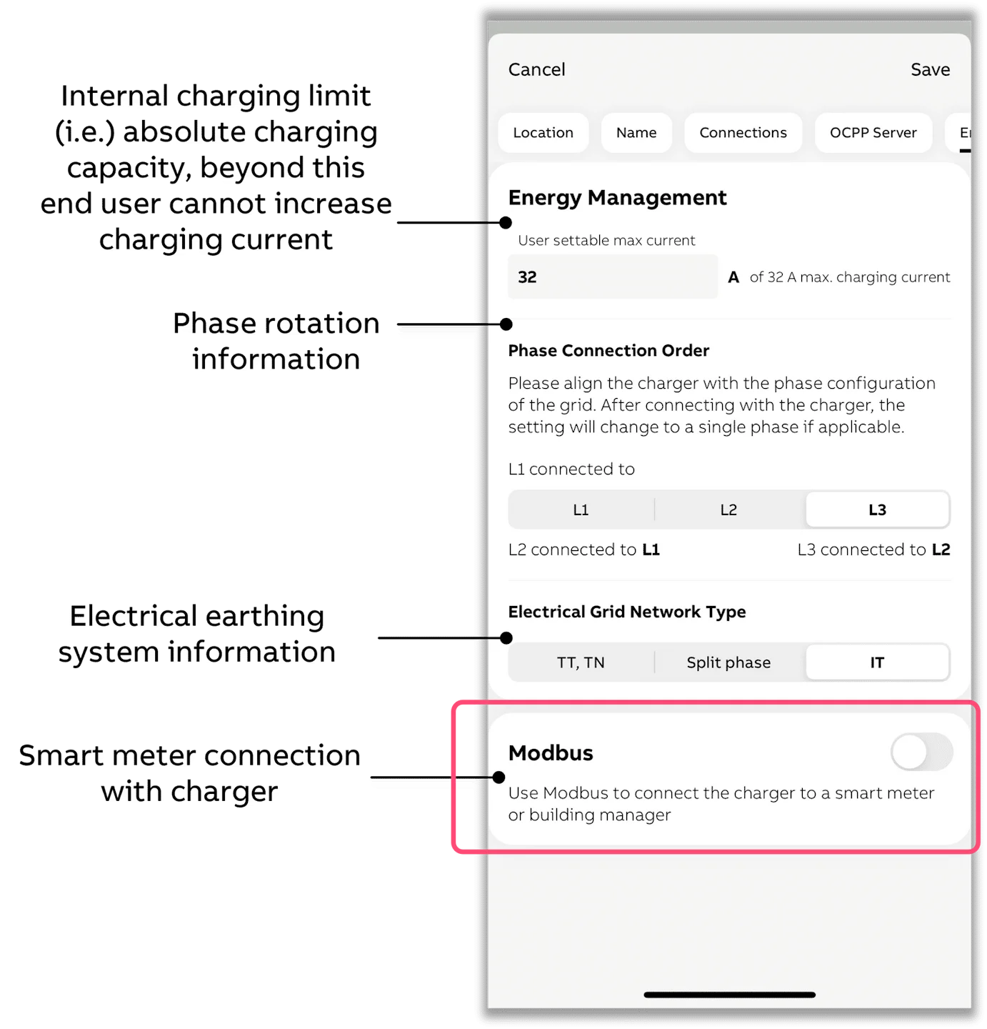
- Select "Local controller" and then "Modbus TCP/IP"
- You must set a fixed IP address in the charging station within the same network range as the controller.
- Important: Always choose 502 as the server port.
- For home and small business networks, a typical setup is with e.g. fixed IP address 192.168.1.50:
- IP address: 192.168.1.50
- Mask address: 255.255.255.0
- Gateway address (the address of your router): 192.168.1.1
- Server Port: 502
Terra Gateway Pro
The Terra Gateway Pro is a site controller, not a charging station. It sits between our EMS and a group of ABB DC chargers, and it is the only device our EMS talks to: the gateway then spreads the budget it receives over the chargers behind it.
Because control happens at site level, our EMS cannot start, stop or limit an individual charger or connector behind the gateway. Everything behind the gateway is monitoring only.
How it works
Our EMS decides one site-wide charging budget and writes it to the gateway over Modbus TCP. The gateway converts that budget into per-charger allocations using its own load management. Each physical charger behind the gateway can have up to two EVSEs (connectors).
The gateway expects our EMS to keep proving it is alive. If it does not see a refresh for 10 seconds or more, it stops honouring the EMS budget and falls back to a safe budget you configure yourself. When that happens, the platform reports it on the device so you can see that the site is no longer being controlled.
Adding the gateway to the EMS
Add a single ABB Terra Gateway Pro EV charger device pointing at the gateway's IP address. The gateway answers on Modbus TCP port 502, slave ID 1.
This integration requires EMS controller version 0.0.320 or later. On an older controller the Terra Gateway Pro does not appear in the device wizard; update the controller first.
You then configure three settings:
| Setting | What to enter |
|---|---|
| Charger unit IDs | The Modbus unit ID of every physical charger behind the gateway, typically 101, 102, 103 and so on. The gateway has no register that lists its own chargers, so they have to be entered by hand. A charger you leave out still charges, but the EMS will not show its data. |
| Grid topology | Whether the site is single-phase or three-phase. The gateway's budget register is a per-phase current, so this is what lets the EMS convert a kW setpoint into the right number of amps (230 V single-phase, 400 V three-phase). Getting this wrong makes the site charge at the wrong power. |
| Fallback maximum current | The per-phase current, in amps, that the gateway falls back to when the EMS link drops. The default is 0 A, meaning no charging until the EMS is back. Raise it only if you want charging to continue unsupervised. |
EMS functionality
With the current integration, our EMS enables:
- Site-level charging budget control across every charger behind the gateway
- Load balancing within the limit of the grid connection, together with the battery and PV
- Charging at the cheapest moments, including during negative prices
- Monitoring per charger: status, model, serial number and number of EVSEs
- Monitoring per EVSE: state, allocated budget, DC current, DC voltage, DC power, state of charge and charged energy
- A warning when the gateway has fallen back to its own safe budget
Additional functionality may be added over time as integration capabilities evolve.