DSO RTU
ORES
DSO RTU with ORES, the Walloon grid operator, over a Modbus RS-485 producer link with absolute power setpoints.
ORES is the distribution grid operator for most of Wallonia and part of the Brussels periphery. The Voltmasters EMS supports DSO RTU with ORES for producer sites, following the ORES specification OPM-080-ST09, the complement to the C2/112 connection prescription.
To use it, set the DSO RTU provider to ORES under Configuration → Grid & market → DSO RTU settings.
ORES requires EMS controller version 0.0.324 or later. On an older controller the option does not appear in the dropdown; update the controller first.
Two things to know before you start
- Safety decoupling does not run over this link. The ORES points carry no emergency stop and no decoupling command. Decoupling on a grid fault is the autonomous C10/21 protection in the installation, entirely outside the EMS. Do not wire or commission anything on the assumption that ORES can stop the installation through the EMS.
- Every value ORES writes is a real instruction. There is no value that means "produce freely": 0 MW means produce nothing. Before ORES has written anything, nothing is imposed at all, which is a different state from a received 0.
Connection
The ORES RTU is the Modbus master and the customer's equipment is the slave. The EMS plays that slave: it serves registers and answers the RTU's polls, and never initiates traffic of its own.
Link parameters
| Parameter | Value |
|---|---|
| Type | Modbus RTU over RS-485 |
| Baud rate | 38400 |
| Data bits | 8 |
| Parity | Even |
| Stop bits | 1 |
| Timeout | 1000 ms |
| Inter-frame gap | 2 ms |
| Slave address | 100 (ORES allows 100 to 120) |
ORES allows one slave address per energy, but also permits several energies to share one address when a single slave manages them all. The EMS is one slave managing everything, so it serves a single shared address, 100.
The RS-485 gateway
The controller has no RS-485 port and serves Modbus TCP, so the link is bridged by a gateway that converts TCP to RS-485. The gateway must be configured as an RTU master on the serial side and a Modbus TCP client toward the EMS: the ORES RTU issues the requests, the gateway forwards them to the controller, and the responses go back out on RS-485. This is the reverse of the usual "serial slave behind a TCP server" setup, so it is worth double-checking during installation.
Use a MOXA MGate MB3180 on firmware version 1.2.2. That is the converter on the ORES approved-material list (OPM-080-ST09, "Liste matériel agréé"), and the firmware version is pinned in that list. Check it on delivery.
Encoding
| Setting | Value |
|---|---|
| Format | Float 32 (every power point spans two registers) |
| Unit scale | 1 point = 1 MW |
| Word order | High word first |
| Reactive sign | Capacitive positive (ST09 §17.4.5.4.2) |
Float 32 with a 1 MW scale is ORES's own recommendation and is the only combination without a range or resolution trap. The EMS works internally in kW and kVAr and converts on the wire, so nothing about these choices is visible on the platform.
The point list
ORES organises a producer site into energies: up to four production blocks, plus the grid connection point. The EMS serves all four production blocks, at fixed register bases twenty registers apart.
| Block | Base register |
|---|---|
| Connection point | 0 |
| Production 1 | 4000 |
| Production 2 | 4020 |
| Production 3 | 4040 |
| Production 4 | 4060 |
Production 1 carries the site's PV. The other three blocks are served so that the RTU always finds a complete map: their measurements read zero, and a setpoint written to them is stored and echoed like any other, but nothing is enforced from it. Storage is not one of ORES's primary sources and carries no setpoint of its own.
Per production block
| Point | Register | Direction |
|---|---|---|
| Measured active power | base + 0 | ORES reads |
| Measured reactive power | base + 2 | ORES reads |
| Active power setpoint | base + 4 | ORES writes |
| Reactive power setpoint | base + 6 | ORES writes |
| Active setpoint echo | base + 8 | ORES reads |
| Reactive setpoint echo | base + 10 | ORES reads |
The two echo registers are a handshake: the EMS serves back the value it last received on the matching setpoint register, so the RTU can confirm its instruction landed. Before the first write there is nothing to echo and the registers read zero.
Connection point
| Point | Register | Direction |
|---|---|---|
| Measured active power | 0 | ORES reads |
| Measured reactive power | 2 | ORES reads |
Watchdog pair
| Point | Register | Direction |
|---|---|---|
| Watchdog generator ORES | 4110 | ORES writes |
| Watchdog generator Voltmasters | 4111 | ORES reads |
These are the only single-word registers in the map. See The watchdogs below.
How an active power instruction is applied
An absolute ceiling on injection
ORES writes an absolute power, negated: a production limitation carries a minus sign on the wire. ST09 §17.4.5.4.4 allows that instruction to be enforced either on the production itself or on injection at the connection point, and the EMS takes the connection point:
injection ceiling = setpoint − site consumption calculated at the moment the instruction was received
This is the path that lets a site comply without throwing energy away. If the setpoint is 4 MW and the site consumes 1 MW, the installation may still produce 5 MW, because only 4 MW reaches the grid. Charging the battery with surplus PV satisfies the ceiling just as curtailing the PV would, and keeps the energy.
The consumption term is pinned at the moment of reception, not tracked live, because that is how ORES's own compliance check works: the calculated consumption is frozen at the instruction's arrival, so the ceiling must not drift with the load afterwards.
In ORES's arithmetic, a charging battery counts as consumption, because storage is not one of its production blocks. This is deliberately different from the way the platform's own dashboards net battery flows out of consumption.
Five minutes before it bites
ST09 §17.4.5.4.3 gives every setpoint a validity delay: an instruction becomes valid five minutes after it is received and stays valid until five minutes after the next one arrives. Compliance at any moment is judged against the setpoint received five minutes earlier.
The EMS follows that rule exactly, which means an instruction that loosens the limit only takes effect after five minutes. Do not read the delay as a fault during commissioning: it is the specification.
No instruction, and a lost link
| Situation | What the EMS does |
|---|---|
| No setpoint received yet | Imposes nothing. ORES has ordered nothing, and 0 MW is a real "produce nothing" rather than an absence. |
| A setpoint stands, the RTU stops polling | Holds the instruction. An order stands until it is countermanded, so ramping back up would be the dangerous choice. The controller raises an issue that the RTU has gone quiet. |
| A setpoint stands, the link restarts | The instruction log survives the restart. A bounce countermands nothing. |
Reactive power
ORES steers reactive power as an absolute kVAr target per energy, not as a band and not as a power factor. The EMS applies it as the PV target of its reactive control and dispatches it open-loop across the PV inverters, respecting each inverter's apparent-power rating. ORES reads the ordered VAr back from the production block, not from the connection point.
- A received 0 is a real order: hold unity power factor.
- No target received yet leaves reactive control on its local behaviour.
- The reactive setpoint carries no validity delay and no consumption term, so it takes effect on the next control cycle.
The watchdogs
ST09 §17.4.5.5 defines a watchdog in each direction: one the operator drives toward the installation, and one the installation owes the operator in return. In both cases the signal is held active while all is well, so that losing the equipment, the wire or the power supply is itself the alarm. Losing the signal is the fault.
Registers by default, contacts optionally
By default the pair runs over the two Modbus registers 4110 and 4111. Bit 0 of each word changes state every second, and no change for ten seconds is the fault. This needs no configuration at all: the EMS watches register 4110 and serves a toggle on 4111 while it is alive.
A value that is rewritten without changing is not a toggle. A generator stuck at 1 that keeps being written is exactly the fault the specification describes, and the EMS treats it as one.
ST09 also allows the pair to be hardwired as potential-free contacts. If your installation is wired that way, assign the two contacts on an IO module under ORES watchdogs in the DSO RTU settings:
| Contact | Port direction | Meaning |
|---|---|---|
| ORES watchdog input | Digital input | The watchdog of the ORES RTU. While it is active, ORES cannot send valid setpoints. |
| ORES watchdog output | Relay output | The watchdog owed to ORES. It stays closed while the EMS is able to receive setpoints. |
Leave a side empty when it is not wired. A configured contact overrides the register source for that direction.
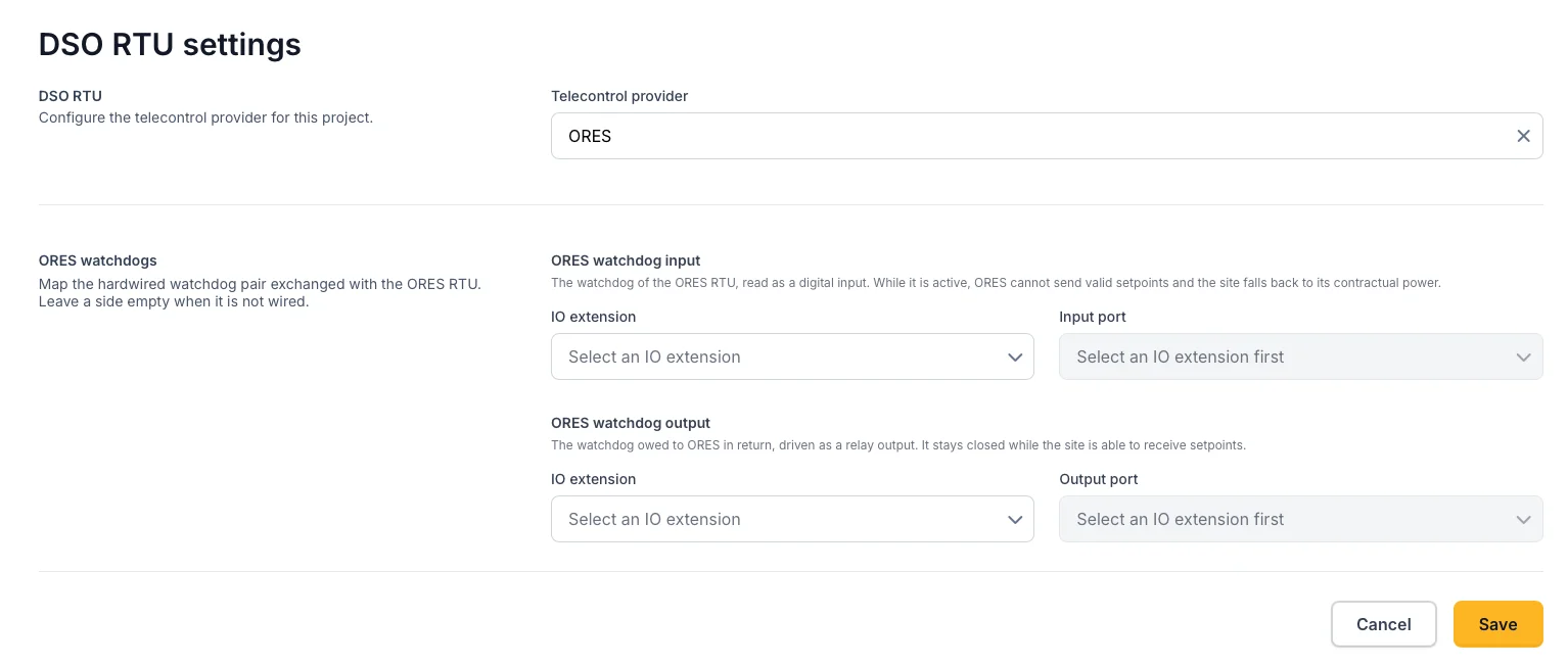
Mapping the two watchdog contacts in the DSO RTU settings.
Wiring the contacts through interposing relays
ORES drives its watchdog contact with 48 VDC or 230 VAC, and the watchdog circuit it expects the installation to close runs at 48 VDC. The IO module can take neither directly: its digital inputs accept 10 to 30 VDC and its relay outputs are rated for 30 VDC. Each direction therefore passes through an interposing relay, so that the module only ever sees its own local 24 VDC.
| Direction | ORES designation | Interposing relay | Wiring |
|---|---|---|---|
| ORES to the EMS (ORES watchdog input) | WD-RTU | Coil matching the ORES signal, for example a Finder 38.51.7.048.0050 with a 48 VDC coil | ORES's watchdog signal energises the coil. The potential-free contact of the relay switches a local 24 VDC signal onto the digital input of the IO module. |
| The EMS to ORES (ORES watchdog output) | WD-PLC | 24 VDC coil, for example a Finder 38.51.7.024.0050 | The relay output of the IO module switches 24 VDC onto the coil. The potential-free contact of the relay closes ORES's 48 VDC watchdog circuit. |
Both relays are energised in normal operation and the contact in use is closed while all is well. Use the contact that closes when the coil is energised, so that a relay dropping out opens the circuit. That carries the logic of ST09 all the way to the wire: a loss of supply, a loss of communication or a fault in the controller de-energises the relay, the contact opens and a watchdog alarm follows, without anything having to act.
On the output side, a controller or network failure only drops the relay if the IO module's own communication watchdog is enabled and the safe status of that channel is set to OFF. Without it the module holds the last state the EMS gave it for as long as it stays powered. This is the same setting as for an emergency-stop output, see Safety and requirements.
When the input is trusted
Because losing the signal is the alarm, an unreadable input is treated as an alarm rather than as "no news":
| Situation | Alarm |
|---|---|
| Not configured | No. The register watchdog is used instead. |
| Configured, but the port cannot be resolved | Yes. The contact cannot be seen. |
| Configured, never read, or the IO module is unhealthy | Yes. Losing contact with the signal is the alarm. |
| Configured and readable | Alarm when the input reads low, meaning the contact is open. |
The output side needs no incident of its own: if it becomes unreachable, the relay de-energises and ORES reads the alarm, which is the design working as intended.
What the alarm does
ST09 says the watchdog must be treated as a setpoint, so a change of state carries the same five-minute delay: the alarm bites five minutes after it appears and instructions resume five minutes after it clears. An alarm that comes and goes inside that window changes nothing.
While the alarm is in force, ORES's instructions are set aside entirely, whatever their value, and the site falls back to its contractual permanent power at the connection point. The EMS takes that value from the project's grid export access power, before any safety margin, so there is nothing extra to configure.
The fallback can be looser than the standing setpoint, not only tighter. A site under a 4 MW setpoint may return to a 7 MW contractual power once the watchdog alarm takes effect. That is the behaviour ST09 prescribes, not a bug.
Independently of all this, the EMS keeps holding injection to the grid limits configured for the project on every control cycle, so the connection is protected whether the watchdog is up or down.
What the EMS reports back
| Register | Source |
|---|---|
| Production measured active power | The PV production of that energy |
| Production measured reactive power | The reactive power of that energy's inverters |
| Connection point active and reactive power | The project's grid energy meter |
| Setpoint echoes | The value last written by the RTU |
A PV inverter that does not report reactive power is published as 0 VAr and raises a warning, because the reactive telemetry then understates what the installation is doing.
Configuring ORES on the platform
- Under Configuration → Grid & market → DSO RTU settings, set the provider to ORES.
- If the watchdog pair is hardwired, wire both contacts through the interposing relays and assign the ORES watchdog input and ORES watchdog output contacts. If it runs over the Modbus registers, leave both empty.
- Check that the project's grid export access power matches the contractual permanent power in the ORES connection contract. That value is the watchdog fallback.
Everything else, the register addresses, the slave address, the format, the unit scale and the word order, is fixed in the controller and matches the ORES validation form. There is nothing per site to transcribe, and therefore nothing to mistype.
Issues the controller reports
| Issue | Severity | Meaning |
|---|---|---|
| ORES link down | Critical | The Modbus slave is not serving, so ORES cannot reach the installation. |
| ORES not polled | Warning | The RTU has stopped polling. A standing instruction is held. |
| ORES watchdog active | Critical | The watchdog alarm is in force, instructions are set aside and the site runs to its contractual power. |
Lab validation test and certification
An ORES producer link is only valid after a lab validation test, performed jointly by an ORES agent and the customer on the actual equipment. The test uses the ORES form "Validation communication Modbus RS 485 producteur" and records the brand and model, the RS-485 parameters, the slave address and, per point, the register address, format and unit.
The form closes with an explicit condition: if the customer changes any of the recorded parameters, the test must be repeated. Treat the validated configuration as frozen for that site. Format, scale, addressing and link parameters are all homologation items.
The ORES approved-material list records equipment that has worked for this Modbus link. It is descriptive, not prescriptive: choosing from it does not exempt an installation from the validation test, and equipment that is not on it is not forbidden. The list already contains comparable topologies, a Linux single-board computer behind a MOXA MB3180 gateway and a Linux gateway, which is exactly how the Voltmasters controller is deployed.
Voltmasters validates the full interface at commissioning and assists during the ORES test. See Commissioning & certification.
Not part of this integration
- Emergency stop, decoupling and breaker position. Absent from the ORES point list. Decoupling is the autonomous C10/21 protection.
- The optional connection-point push registers. ORES can supply its own connection-point metering instead of reading ours. The EMS serves the read block, which is the natural fit because the project always has a grid energy meter.
- A setpoint on storage. Production 1 carries the site's PV; the battery is steered by the EMS to comply with the injection ceiling, not by an ORES setpoint of its own.
Next steps
- How DSO RTU works for the general control model.
- RTU connection for the on-site connection and network requirements.
- IO module for the module that carries the hardwired watchdog contacts.
- Commissioning & certification for the validation process.