Device integrations
Reactive power control (Data Manager)
Enabling reactive power control on an SMA Data Manager, and why the total plant power decides what every setpoint means
The EMS sends the plant a reactive power setpoint as a percentage over Modbus. The Data Manager receives it and forwards it to its inverters. Nothing happens until reactive power is enabled as a grid management service in its own right: active power and reactive power are configured separately, and enabling one does not enable the other.
A missing configuration is silent. The Data Manager accepts every write to the reactive power register without a Modbus error and simply ignores it. The only symptom is that the plant keeps delivering zero reactive power.
Use the Data Manager's own web interface
Log in to the Data Manager directly on its IP address, as Installer.
The grid management service menu does not appear in Sunny Portal. Installers who look there conclude the function is unavailable on the plant, which is not the case. Open the Data Manager on the local network instead.
Enable reactive power
Configuration > Grid management service
The overview lists the services separately. Reactive power shows Configuration & activation while it is still unconfigured, and Active once it is done.
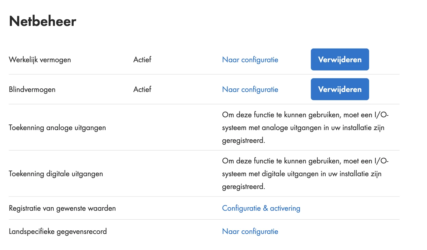
In the Dutch interface: Configuratie > Netbeheer, row Blindvermogen, button Configuratie & activering.
Select Configuration & activation on the reactive power row and walk through the installation assistant:
Total plant power
Check this value before anything else, see the section below.
Operating mode
Choose Open-loop control. Closed-loop control needs an energy meter at the point of interconnection and stays greyed out without one.
Setpoint source
Choose Reactive power, Modbus. The cos phi options and the Q(U) curve are greyed out without a meter at the point of interconnection; a plain reactive power setpoint does not need one.
Rate of change and fallback
Leave the rate of change off unless the grid operator requires a ramp. The fallback defaults to a timeout of 600 s and a fallback value of 0 %, which is a sensible choice: the EMS refreshes the setpoint every few seconds, so the fallback only fires when the EMS is genuinely gone.
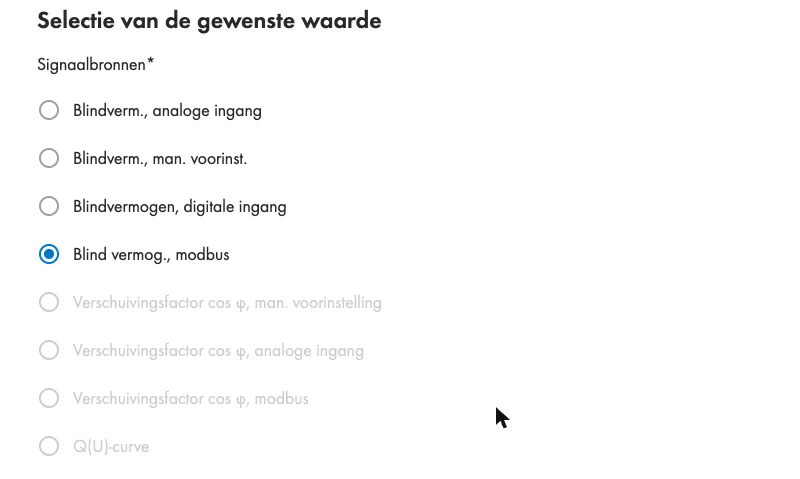
In the Dutch interface the setpoint source is called Blind vermog., modbus, and the operating mode Besturing (open-loop) versus Regeling (closed-loop).
After saving, the assistant warns that control begins once the setpoint has been transmitted at least once. That is expected: the EMS starts writing on its next control cycle.
The total plant power decides what a percentage means
Both the active and the reactive power setpoint are sent as a percentage. The Data Manager converts that percentage using Total plant power, the field in the first step of the assistant. It is a manually entered value, and nothing verifies it against the inverters that are actually connected.
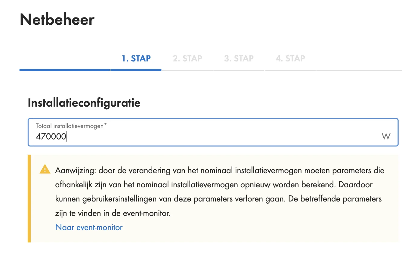
If this value does not match the plant, every setpoint is wrong by the same ratio, in both directions, without any error anywhere.
On a 470 kW plant this field had been left at 220 000 W. A curtailment command of 25 % produced 55 kW instead of the expected 117.5 kW, because the Data Manager applied 25 % of 220 kW. Correcting the field to 470 000 W made the same command produce 70 kW at 15 %, exactly as expected.
Make sure the value matches the plant's installed inverter power, and that the same number is entered as the device's rated power in our platform. Registers 30233 and 31547 report the inverter power the Data Manager itself has detected, which is a useful cross-check.
Changing the total plant power recalculates every parameter derived from it, and SMA warns that user settings on those parameters can be lost. Note what is configured before changing it, and check the event monitor afterwards.
Verify on the plant
Configuration alone is not proof. Command a modest setpoint and measure what the plant does:
| Register | Meaning |
|---|---|
| 30805 | Reactive power delivered by the plant, in var |
| 32185 | Reactive power specification currently applied, in percent |
| 31239 | Active power limit received over communication, in percent |
As long as the EMS has never written, 31239 reports the SMA "value not available" sentinel rather than zero. Once the EMS writes, both registers follow the commanded percentage within seconds. If they follow it while 30805 stays at zero, the Data Manager accepts the setpoint but the inverters do not act on it.
Check that the inverters agree on the reference
The Data Manager forwards a percentage, and each inverter applies it to a reference of its own choosing. Inverter families do not necessarily agree on that reference, so the plant can deliver a different amount of reactive power than the percentage implies.
On a plant combining two Sunny Tripower CORE2 with two STP 125-70, a command of 10 % produced 78 kvar where 47 kvar was expected. The CORE2 units followed correctly, at 10 % of their own maximum reactive power. The STP 125-70 units delivered roughly four times their share, which lifted the plant total by a factor of 1.66.
Always measure the delivered reactive power against a known command before relying on the setpoint, particularly on a plant that mixes inverter families or connection types. Two or three points are enough to establish the ratio, and the response is linear.
Per inverter, the relevant setting is the reactive power mode and its reference quantity, see Sunny Boy / Sunny Tripower.