Device integrations
Industrial meter (A1 port only)
Connect a Fluvius industrial meter to the Voltmasters EMS controller through its A1 port, for medium and high voltage installations.
Industrial meter (A1) installation guide
This guide applies only to installations using an industrial meter connected via the A1 port, typically found in medium- or high-voltage systems.
Step 1: Physical connection
Connect the industrial meter to the Controller using the designated A1 interface as specified by the meter manufacturer.
- Verify that the A1 wiring is correctly terminated
- Ensure polarity and phase order are respected
- Confirm the Controller is powered on before configuration
Step 2: Add the A1 meter to the system
When registering a new A1 meter in the system, you will be prompted to configure scaling factors. These parameters are critical for accurate measurements and must match the transformer ratios used in the installation.
Step 3: Configure scaling factors
Industrial meters measure secondary values from transformers. The system converts these into real-world values using scaling factors.
Voltage Scaling Factor
- Represents the ratio of the voltage transformer (TP)
- Default value: 110.0 V
- Adjust only if a voltage transformer is present
- Example
If the installation uses a 15400 V / 110 V Voltage transformer, the correct voltage scaling factor is:
15400 ÷ 110 = 140
Current Scaling Factor
- Represents the ratio of the current transformer (TI)
- Default value: 5.0 A
- Example
If the installation uses a 100 A / 5 A current transformer, the correct current scaling factor is:
100 ÷ 5 = 20
Total scaling factor
-
Represents the ratio of the current and voltage transformers together.
-
Example
If the installation uses a 140 (TP) x 20 (TI) transformer, the correct total scaling factor is:140 x 20 = 7000
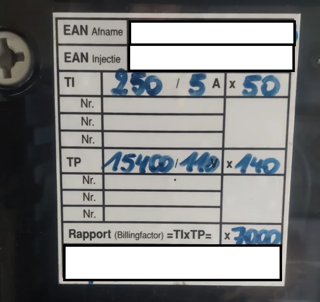
Step 4: Verification
After configuration, verify correct operation:
- Check that voltage, current, and power values are displayed
- Compare readings against known reference values or utility data
- Confirm phase balance and direction of power flow
Troubleshooting
| Issue | Likely Cause & Resolution |
|---|---|
| No data from meter | Incorrect A1 wiring or communication settings; verify connections and meter protocol |
| Values too high or too low | Scaling factors do not match TP/TI ratios; recheck transformer specifications |
| Negative or reversed power | Phase order or TI polarity is incorrect; verify installation wiring |
| No Voltage displayed | Some older meters (DSMR 2.2) or specific brands (Landis+Gyr) do not send voltage data. This is a limitation of the meter itself, not the controller. |
| Unstable readings | Loose connections or incorrect grounding; inspect wiring and shielding |
Notes for installers
- Always document CT/PT ratios