DSO RTU
Configuring Fluvius telecontrole
Every setting a Fluvius telecontrole connection needs on the platform, in the order to configure them, with the documents each value comes from.
Fluvius decides what it expects from an installation in three documents: the study document (studiedocument) that says which flex products apply and which installations sit behind the Netflex cabinet, the zone sheet (zonefiche) of the congestion area, and the single line diagram on which the cabinet is drawn. Every setting on this page transcribes one of those documents. Keep them at hand, because a value that does not match them fails the certification, however well the installation behaves.
Almost everything lives on one page: Configuration → Grid & market → DSO RTU settings. Two settings live elsewhere and are covered at the end: the access powers under Grid settings and the IO module ports.
The order below is the order in which the values depend on each other. The provider unlocks the form, the flex scope decides which sections matter, and the measurement channels and reference powers only make sense once the scope is known.
What applies to your connection
Every Netflex connection needs the base configuration. What comes on top depends on the flex products the study imposes, so check that first: it decides which sections matter and which stay empty.
| Your connection | Steps to walk through |
|---|---|
| Telecontrole only, no flex product | 1, 2, 5, 6, 8 and 9. Technical flex stays off and the asset reference powers stay empty. Fluvius steers only the connection point. |
| With technical flex | The same, plus 3 (switch technical flex on) and 4 (the two reference powers). The production channels in step 5 are now in scope. |
| With Fall-Back Flex | The same as telecontrole only, plus the registered flexible consumption power in 3 and the whole of 7. |
A connection can have both flex products; then everything on this page applies.
Before you start
Collect from the customer and the installer:
- The study document: whether technical flex is imposed (steering of the assets through
MAXSETAPandMINSETAP), and which installations Fluvius counts behind the cabinet. - The zone sheet: the registered flexible consumption power for channel 6, and the Fall-Back Flex parameters when the connection has that formula.
- The single line diagram with the Netflex cabinet: it is leading for the certification. An installation drawn behind the cabinet is registered; one drawn outside it is not.
- The reference powers from the Fluvius DER register, when technical flex applies. Ask Fluvius for them; they are not the nameplates of the equipment. See asset setpoints.
- The contractual access powers of the connection, import and export.
1. Select the provider
Set Telecontrol provider to Fluvius Netflex. The rest of the form appears once a provider is selected. If the option is missing, the controller runs a version that does not support it yet; update the controller first.

The provider selection at the top of the DSO RTU settings.
Selecting the provider starts the IEC-104 server on the controller and lets the Fluvius RTU connect. The physical link is described in RTU connection; the controller's address on the RTU link is filled in by the platform, see Network configuration.
2. Emergency stops
Fluvius has two emergency stops, one for production (injection) and one for consumption (offtake). The form has a block per side, each with two lists:
| List | What it holds |
|---|---|
| Triggers | What switches this stop on. The Fluvius signal is built in and cannot be removed. Add trigger adds a digital input on an IO module, for instance a stop button or a protection contact, that switches the same stop on locally. |
| Emergency stops | What is activated to carry out the stop. Add output port adds a relay output on an IO module that is driven to its stop state; wire it into the coupling of the assets that have to stop. Several outputs per side are allowed, for instance one per cabinet. |
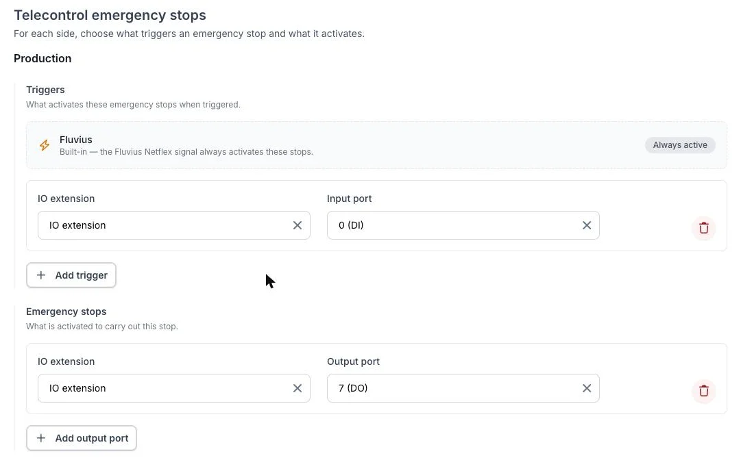
The production side of the emergency stops: the Fluvius signal as built-in trigger, an extra stop input on port 0 of the IO module, and relay output 7 that carries out the stop.
The software stop always runs, whatever is configured here: on a production stop the EMS sets PV to zero and the battery to 0 kW, on a consumption stop the battery to 0 kW and the controllable loads off. The relay outputs add the physical disconnection Fluvius expects. How to wire a relay as a hold circuit, which actuation mode to pick and what the module's own watchdog must be set to is on Emergency stop.
Fluvius expects the unit to be physically disconnected after a stop signal, through a switch. Treat a relay output per stop as a requirement of a Netflex connection, not as an option. The software stop alone is not what the inspector tests.
3. Flex according to the study
This section transcribes the study document and decides which measurement channels Fluvius expects.
| Field | What to enter |
|---|---|
| Technical flex imposed | On when the study imposes technical flex, so when Fluvius steers the assets with MAXSETAP and MINSETAP. Only then does Fluvius expect measurements in the production channels (solar, wind, CHP, storage, other production). |
| Registered flexible consumption power | Only when the connection has a flex product that registers flexible consumption, in practice Fall-Back Flex. The power the zone sheet registers for channel 6, in kVA. It is not in the study document; ask the customer for the zone sheet. The form uses it to check the channel 6 configuration below. |
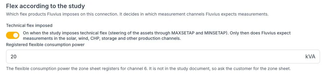
The flex scope: technical flex on, and 20 kVA of flexible consumption registered for channel 6.
Without technical flex, Fluvius only steers the connection point (MAXSETP, MINSETP) and only expects channels 5 and 6. The asset reference powers and the production channels then play no role, and the form says so when a device is assigned to a channel the dossier does not expect.
4. Asset reference powers
Only with technical flex. The two powers Fluvius registered for the site, which MAXSETAP and MINSETAP are percentages of:
| Field | Base for | Counts |
|---|---|---|
| Consumption reference power (kW) | MAXSETAP |
The batteries only |
| Production reference power (kW) | MINSETAP |
The batteries and the PV |
Enter the values from the Fluvius DER register, not the nameplates. Left empty, the EMS falls back to the installed power of the assets it steers, which keeps the site safe but does not match the inspector's arithmetic. The full reasoning, a worked example and the certification checklist are on Asset setpoints.

The two reference powers, one per direction.
5. Netflex measurement channels
Fluvius registers a power per measurement channel and expects measurements only in the channels that registration covers. The Netflex measurement channels card lists every device that can carry a measurement and the channel it is reported in.
| Channel | Category | Default for |
|---|---|---|
| 1 | Solar | PV inverters |
| 2 | Wind | Wind turbines |
| 3 | CHP | (no default) |
| 4 | Storage | Batteries |
| 5 | EV charging | EV chargers |
| 6 | Flexible consumption | Controllable loads |
| 7 | Other production | (no default) |
| 0 | Not reported | Devices outside the registration |
Every device starts in the channel that matches its type. Change it when the dossier says otherwise:
- A battery that Fluvius registered as flexible consumption belongs in channel 6, not in channel 4.
- EV chargers always go separately in channel 5, never in channel 6.
- An asset that is not part of the flex registration, for instance PV that is not drawn behind the cabinet, is set to Not reported. Fluvius then receives no measurement for it.
The summary cards show the installed power and the number of devices per channel. Two checks run on the configuration: a warning when devices sit in a channel the dossier does not expect (production channels without technical flex), and a comparison of the power configured in channel 6 with the registered flexible consumption power from the zone sheet.
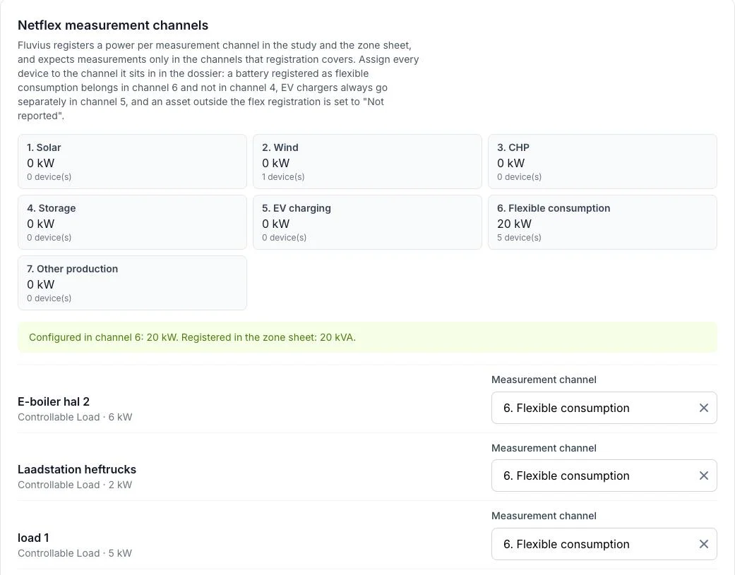
The measurement channels: one card per channel, the coverage check against the zone sheet, and the channel of each device.
The channel is not a reporting preference. Fluvius compares the sum of channels 1, 2, 3, 4 and 7 with MINSETAP and MAXSETAP, and it judges the installation on what arrives in those channels. A device reported in a channel it is not registered in, or a registered device that is missing, fails the test.
6. The registered asset group
Below the channels, the Devices for telecontrol table lists the PV inverters and batteries with a switch that says whether the device belongs to the asset group Fluvius registered behind the cabinet. That membership decides whether the device counts at the virtual asset coupling point and whether the telecontrol laws steer it. See counted versus steered for what the switch does and does not mean.
Three settings have to tell the same story about the same diagram: the measurement channel of a device, its membership of the asset group, and the reference powers. A PV that is not drawn behind the cabinet is Not reported, outside the asset group, and absent from the production reference power. A PV that is drawn behind it is in channel 1, inside the group, part of the reference power, and steerable. Fluvius does not accept a mix, such as a PV that is reported only to offset the battery, and the measurement channels card flags the two halves of that mix: a device in the asset group that is not reported in an asset channel, and a device in an asset channel that is outside the group.
A device in the asset group has to be steerable by the EMS. A registered PV or battery in unmanaged mode raises the warning Registered telecontrol asset cannot be steered on the project. Either enable control on the device, or take it out of the group when it is not behind the cabinet.
7. Fall-Back Flex
Connections with the Fall-Back Flex formula enable it in the same form: Fall-Back Flex active, the reduced power P_red, and for day-ahead zones the planning API settings. Fall-Back Flex covers the formula, the configuration fields and the monitoring.
8. Access powers under Grid settings
MAXSETP and MINSETP are percentages of the contractual capacity of the connection. The EMS takes that capacity from Configuration → Grid & market → Grid settings: the access power for consumption is the base of MAXSETP, the access power for injection the base of MINSETP. Enter the contractual values, before any safety margin. For a Fall-Back Flex connection the import access power is P_base from the bid form.
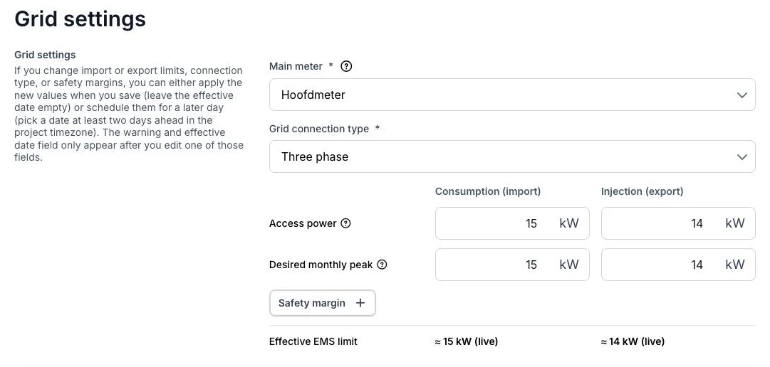
The access powers are the 100 % of the connection point setpoints.
9. The IO module ports
The relay outputs and inputs assigned in step 2 are shown on the Ports page of the IO module (Configuration → Devices, open the module). The diagram shows which port carries which function, and the table below it shows the actuation mode of each relay output. Check here that every emergency stop has a port and that the actuation mode matches the wiring.
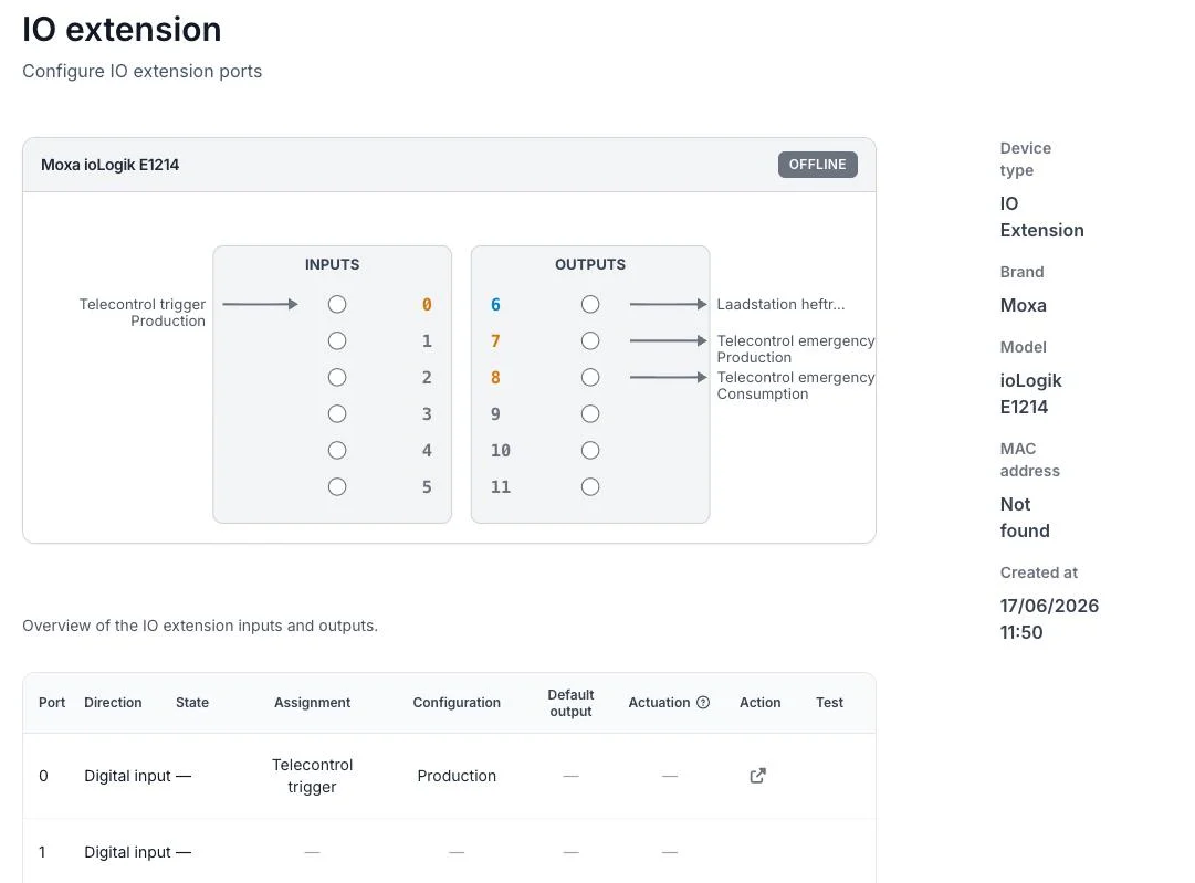
The Ports page of the IO module: input 0 triggers the production stop, outputs 7 and 8 carry out the production and consumption stops, output 6 switches a controllable load.
Checklist before the certification
- [ ] Provider set to Fluvius Netflex, and the DSO RTU dashboard shows a recent snapshot with every setpoint at 100 %.
- [ ] Both emergency stops have a relay output that physically disconnects the assets, and the module's watchdog and safe state are set.
- [ ] Technical flex matches the study document, and the registered flexible consumption power matches the zone sheet.
- [ ] With technical flex: both reference powers come from the Fluvius DER register.
- [ ] Every device is in the channel of the dossier, devices outside the registration are Not reported, and the channel 6 coverage check is green.
- [ ] The asset group agrees with the single line diagram, and no registered device is unmanaged.
- [ ] The access powers under Grid settings equal the contractual capacities.
- [ ] Every device Fluvius may steer is controllable in the EMS.
Commissioning and certification describes how the test itself runs and how to follow the values on the DSO RTU dashboard while the inspector sends them.