Device integrations
Controllable loads
Switch a simple on/off load (heating element, pump, auxiliary equipment) through a relay output of an IO extension, managed by the EMS control strategy.
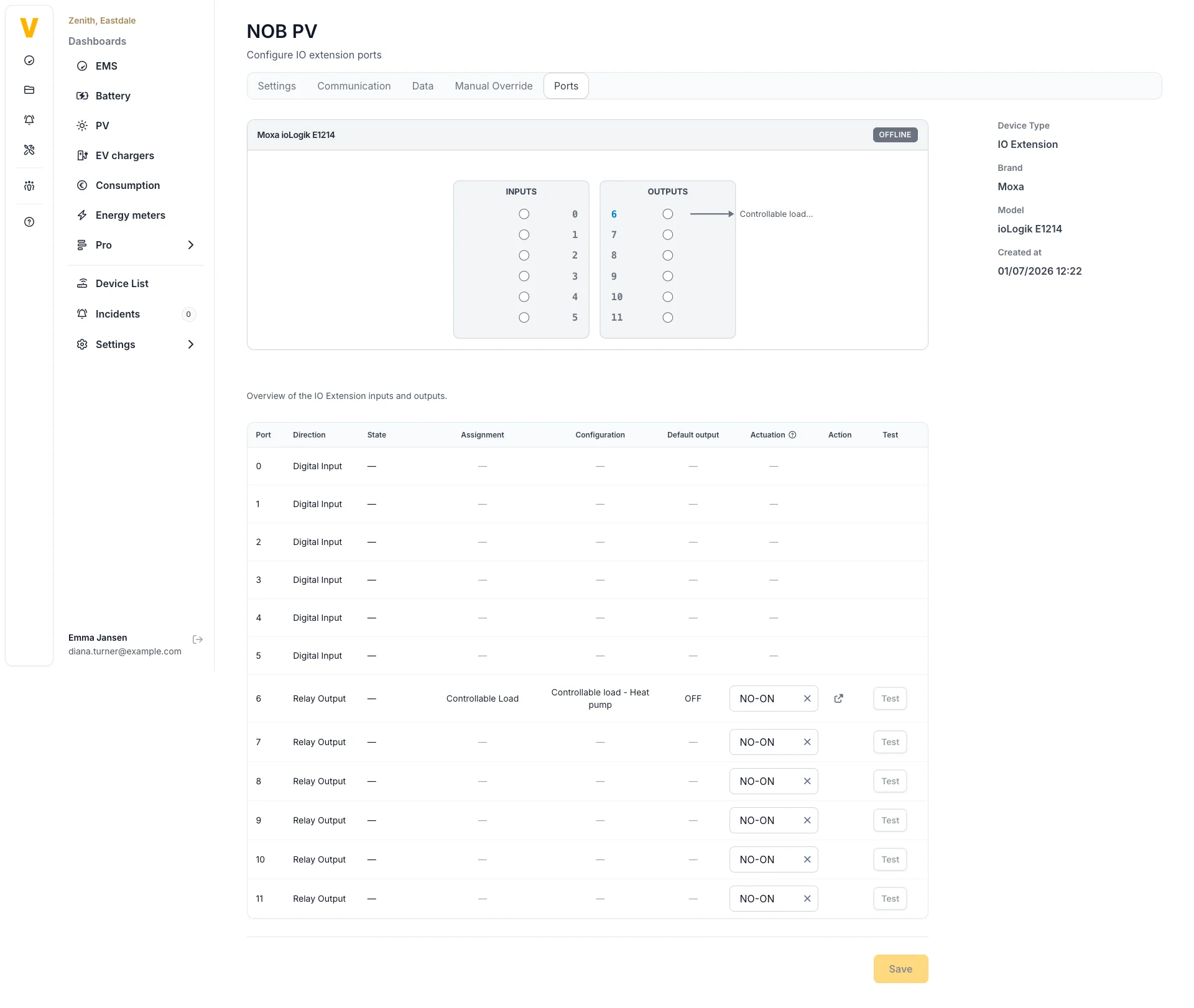
Voltmasters EMS: Controllable load via IO module
A controllable load is a simple on/off load, for example a heating element, a pump or other auxiliary equipment, that the Voltmasters EMS can switch on and off. The load is wired to a relay output of an IO module, and the EMS decides when to switch it as part of the local control strategy (self-consumption and cost optimization), and switches it off on a DSO RTU emergency stop consumption.
Use a controllable load to absorb PV surplus in your own installation, for example to heat water when there is more solar production than the rest of the site consumes, instead of injecting it into the grid.
Supported models
| Model | Connection |
|---|---|
| On/off load | Relay output of an IO module |
Requirements
- An IO module with a free relay output, added and reachable on the platform.
- EMS controller version 0.0.277 or higher.
Adding a controllable load
Add the controllable load like any other device:
- Device type: Controllable load
- Model: On/off load
- Connection: via an IO extension, select the IO extension device and the output port the load is wired to.
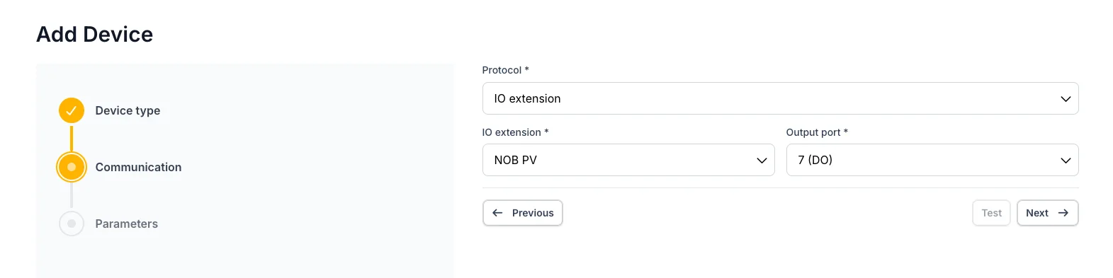
Selection of the IO extension device and the ouput port for the load
The same relay output cannot be shared with another function (for example a telecontrol emergency switch).
Relay wiring and default state
Check the relay rating before wiring the load. A relay output can only switch a limited current and voltage. Anything above that rating, any 400 V three-phase load and any inductive load with a significant inrush (pump, fan, motor) must be switched through an interposing contactor, with the relay output driving only the contactor coil. The ratings are in IO module: technical specifications.
How a switch command maps to the relay depends on two settings:
- Relay actuation mode: how the load is wired to the relay contacts, and what the closed contact means:
| Relay actuation mode | Load is ON when… |
|---|---|
| NO, ON when closed | NO contacts are closed |
| NO, OFF when closed | NO contacts are open |
| NC, ON when closed | NC contacts are closed |
| NC, OFF when closed | NC contacts are open |
- Default output state: the state the output falls back to (On or Off, default Off). This is the safe state used when no active command applies.
Control parameters
The EMS uses the following parameters to decide when to switch the load. They are set when adding the device and can be changed later in the device's general settings.
| Parameter | What it does |
|---|---|
| Nominal power | The rated power of the load, in kW. |
| Activation power | Minimum PV surplus required to switch the load on. If unknown, use the same value as the nominal power. |
| Priority | Activation order from 1 (highest) to 10 (lowest). Higher-priority loads are switched on first when available power is limited. |
| Minimum runtime per activation | Minimum time the load stays on once switched, to prevent frequent on/off cycling. |
| Minimum runtime per day | Minimum total runtime per day, to ensure the load runs enough for proper operation. |
| Deadline hour | Latest hour (0–23) by which the load should have completed its daily runtime. |
Setting Controllable to off on the device turns it into a monitoring-only device: the EMS reads it but never switches it, and it is excluded from the control strategy.
How the EMS controls the load
- In self-consumption and cost optimization, the EMS switches the load on when there is enough surplus power (above the activation power), respecting priority when power is limited, and honours the minimum-runtime and deadline parameters.
- On a DSO RTU emergency stop consumption, all controllable loads are switched off. See How DSO RTU works.
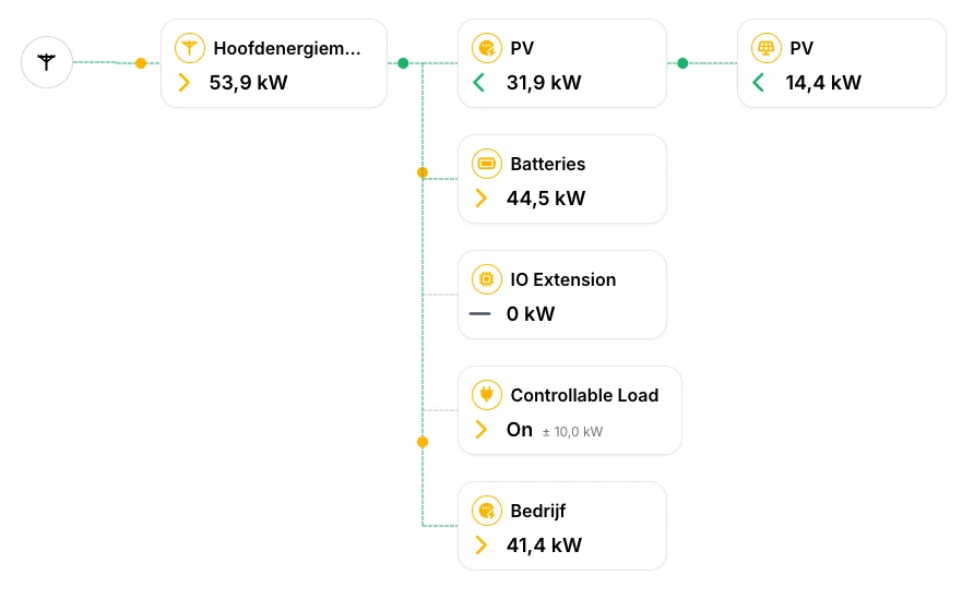
The power shown here is the nominal power you configured for this controllable load, not a measured value. Because the load has no power metering of its own, this figure (marked with ±) is an estimate of its effective consumption while it is switched on.
Manual override
A controllable load can be manually overridden to a fixed active state (On or Off), for example for testing or maintenance. The override takes precedence over the automatic control; clear it to return the load to the control strategy.
See also
- IO module: the device that provides the relay output.
- IO module: technical specifications: contact ratings and what a relay output may switch directly.
- Emergency stop: the other use of an IO module's relay outputs.