DSO RTU
Emergency stop
Placing, wiring and configuring an IO module so a DSO RTU emergency stop is also executed physically, in hardware.
For installations that require a physical emergency stop, the DSO RTU emergency-stop signal can drive one or more relay outputs on an IO module. When the grid operator triggers an emergency stop, the EMS drives the configured relay output(s) to their stop state. Those relays are wired into the installation's emergency-stop circuit.
This is the hardware layer described in How DSO RTU works. It is in addition to the software stop; assets are always curtailed in software as well.
Use the IO module when a stop must be enforced independently of the asset's own communication, for example to drive an external contactor, an EPO loop, or the emergency-stop input of switchgear.
The IO module can do two things for emergency stops:
- Carry out an emergency stop: a relay output (DO) is switched to its stop state. Most of this page is about this.
- Trigger an emergency stop: a digital input (DI) connected to a physical contact (such as a stop button) can switch the emergency stop on by itself, on top of the one the grid operator can send. See Triggering an emergency stop below.
What the relay may switch
The relay outputs are potential-free, normally-open contacts that you wire into the installation's safety or stop circuit. Use them to command a contactor or a safety relay, not to switch the load itself. The contact ratings, and what needs an interposing contactor, are in Technical specifications.
Switching is not instantaneous: the EMS re-evaluates the outputs every control cycle (roughly 1 s) and the relay itself takes up to 1500 ms.
Place the IO module
Where the module goes, and how many modules you need, depends on the physical layout of the installation. A relay must be wired to the asset or switchgear it has to stop, so a module is placed close to those assets; an installation spread over several cabinets therefore needs a module in each cabinet that has to be stopped.
See Placement and cabling for the full placement and cabling guidance. Note each module's IP address, port and Modbus slave ID, since you need them when adding the device on the platform.
Wire the emergency stop
- Assign one or more relay outputs to each emergency-stop action you want to enforce (production and/or consumption). Several outputs can act on the same action, useful to stop multiple assets or cabinets at once.
- Wire each relay into the emergency-stop / EPO input of the asset it has to stop, or into the coil circuit of the contactor or breaker that couples it.
Recommended wiring: the NO contact as a hold circuit. The IO extension's relay outputs are normally open only, with two terminals per channel (R0_NO and R0_C up to R5_NO and R5_C); there is no NC terminal. Wire that NO contact so it keeps the installation enabled: the EMS holds the relay energized, the contact stays closed, and the asset may run. An active stop de-energizes the relay, the contact opens and the asset stops. Set the port's relay actuation mode to NO-ON, which is the default. Losing the module's 24 VDC supply, or the relay wiring itself, then opens the contact the same way.
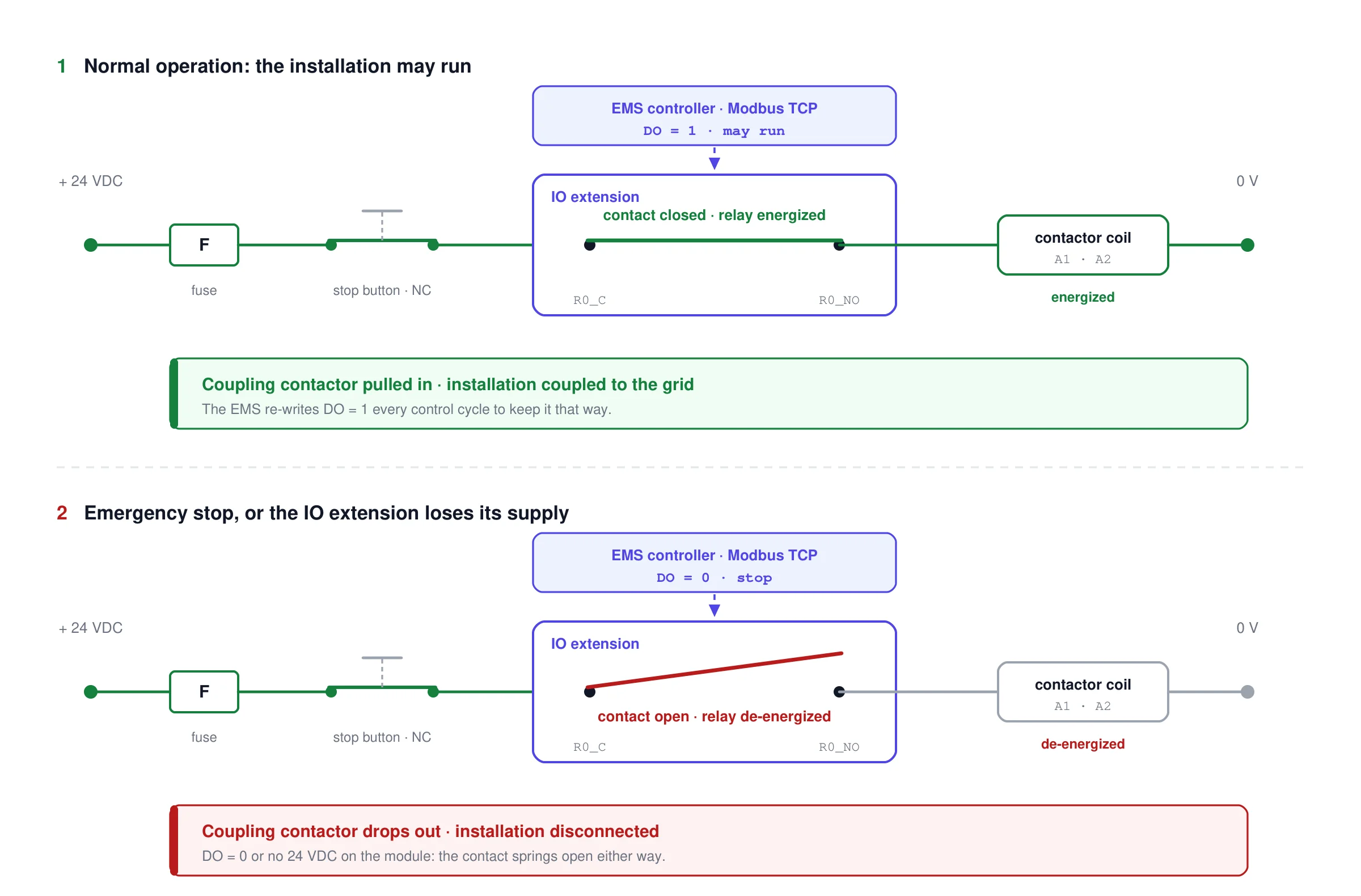
The relay output is one link in a series hold circuit. The EMS keeps the contact closed while the installation may run, so the contactor coil stays energized and the coupling stays closed. An active stop, or the loss of the module's supply, opens the contact and the coupling drops out.
Check what the receiving side does with an open contact. This is only failsafe if the asset actually stops on an open circuit: an enable input, an EPO loop that has to be closed to run, or the coil of the contactor that holds the coupling closed. If the input instead needs a closed contact to stop, an NO contact cannot deliver that when it loses power. Use an interposing relay to obtain a normally-closed contact (the port is then NC-OFF), or an energize-to-stop mode with the module's watchdog as the safeguard (see Safety and requirements).
What that looks like in a disconnection board. The relay's NO contact sits in the control circuit that energizes the coil of the coupling contactor, or the undervoltage release of the breaker. Contact closed means coil energized and the coupling stays closed. When the EMS opens the contact the coil drops out and the breaker opens, so the installation is disconnected. Everything that interrupts that same circuit has the same effect: an active emergency stop, a stop button in series with the contact, a broken wire, and the IO module losing its 24 VDC. Check whether the switchgear recloses on its own once the contact closes again, or whether it needs a separate reset or close command, because that decides whether someone has to go on site after a stop.
The actuation mode only tells the EMS what a closed contact means; it does not change the hardware. NO-ON and NC-OFF are both de-energize to stop and drive the relay with exactly the same value, and so are NO-OFF and NC-ON for energize to stop. Pick the one that matches the contact you actually wired, so the configuration still describes the installation when someone else reads it. See Behaviour.
Configure the IO module on the platform
1. Add the IO module as a device
- Device type: IO Extension
- Connection: Modbus TCP/IP, with the module's IP address, port and slave ID.
- For the brand and model to select, see IO module.
2. Assign the emergency-stop output(s)
Open Configuration → Grid & market → DSO RTU settings. The emergency stops have a block per side, Production and Consumption. Under Emergency stops, click Add output port, pick the IO module and the relay output (DO) you wired. Several outputs per side are allowed, for example one per cabinet, and you can configure only the side you need.
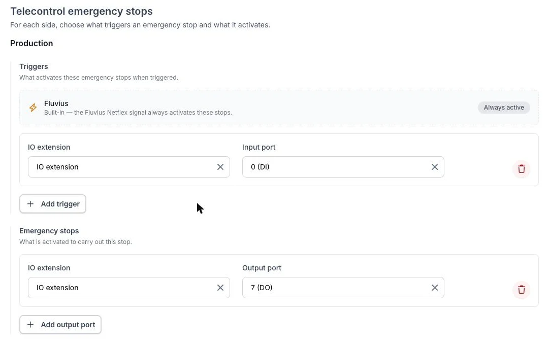
The production side: the grid operator's signal as built-in trigger, an extra stop input, and the relay output that carries out the stop.
The relay actuation mode of each output is set on the device's Ports page, where the assigned function is also shown. Use NO-ON for the recommended hold-circuit wiring above; it is the default. Only choose another mode when the wiring genuinely differs, and see Behaviour for what each one means.
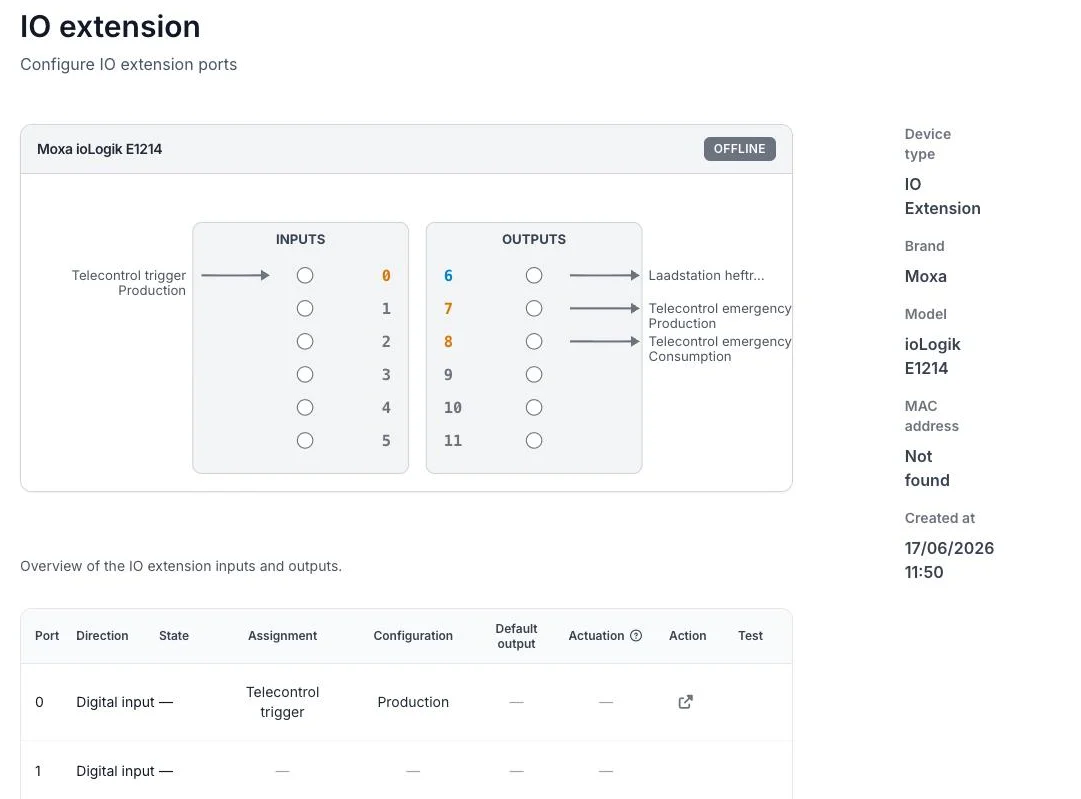
The Ports page of the IO module shows the function of every port: input 0 triggers the production stop, outputs 7 and 8 carry out the production and consumption stops.
The configuration is delivered to the EMS controller automatically as part of the project configuration; no manual controller changes are needed.
3. Set the IO extension's own failsafe
This part is not on the platform. In the module's web console, enable the communication watchdog with a timeout, and set the DO safe mode status of every emergency-stop channel to its stop value (OFF with the NO-ON wiring above). Both are off by default, and without them a controller or network failure leaves the relay untouched. See Safety and requirements.
Behaviour
An output under Production acts on emergency stop production; an output under Consumption acts on emergency stop consumption. When the relevant stop is active, the EMS commands the asset OFF; when it is cleared, the asset is allowed to run. The relay actuation mode translates that into the digital-output value, so the relay can be wired either way:
| Relay actuation mode | Relay on active stop | Relay when cleared |
|---|---|---|
NO-ON: NO contacts, on when closed (default) → de-energize to stop |
De-energized (open, 0) | Energized (closed, 1) |
NC-OFF: NC contacts, off when closed → de-energize to stop |
De-energized (0) | Energized (1) |
NO-OFF: NO contacts, off when closed → energize to stop |
Energized (closed, 1) | De-energized (open, 0) |
NC-ON: NC contacts, on when closed → energize to stop |
Energized (1) | De-energized (0) |
The relay state is re-evaluated every control cycle (≈ 1 second), so it follows the DSO RTU state with sub-second latency. When several outputs are mapped to the same stop they are all driven together. Outputs that are not assigned to an emergency stop are unaffected and remain available for other uses.
Triggering an emergency stop (digital input)
A trigger is a digital input (DI) wired to a physical contact (a stop button, a safety relay, a protection contact) that switches an emergency stop on. It is an extra way to start the same emergency stop the grid operator sends: the emergency stop is on if either the grid operator or any trigger calls for it. You can add several triggers to one emergency stop (production or consumption); any one of them is enough.
Wire it "the quiet way round": the emergency stop turns on when the input goes low. So the contact should hold the input high in normal operation and pull it low for an emergency stop (e.g. a normally-closed contact that opens).
If the IO module can't be reached, its triggers do nothing. A "low" reading only counts as an emergency stop when the EMS has actually read it from a reachable, healthy module. Otherwise an offline or not-yet-read input (which also looks low) could trip the installation by mistake. So one lost connection never starts an emergency stop on its own; the emergency stop stays as set by the grid operator and any working triggers.
To set one up: in Configuration → Grid & market → DSO RTU settings, go to the side you want (Production or Consumption) and, under Triggers, click Add trigger, then pick the IO module and its input port (a Digital Input). The grid operator's own signal is always there as a built-in trigger and can't be removed.
Safety and requirements
A de-energize-to-stop mode covers power loss, not communication loss. The relays are Form A (normally open), so losing the module's 24 VDC opens every contact and the installation goes to its stop state without the EMS doing anything.
It does not cover a controller crash or a broken network while the module stays powered. The module then simply holds the last relay value it was given: a relay that was closed stays closed and the installation keeps running. The module's communication watchdog is disabled by default, and while it is disabled the per-channel safe status has no effect at all.
So configure both, in the module's web console, for every relay output that carries an emergency stop, whichever actuation mode it uses:
- Enable the communication watchdog with a timeout. The EMS polls the module every control cycle, so the watchdog stays satisfied as long as the controller is alive and reachable.
- Set the DO safe mode status of that channel to the value that means stop:
OFFfor a de-energize-to-stop mode (NO-ON,NC-OFF),ONfor an energize-to-stop mode (NO-OFF,NC-ON).
With an energize-to-stop mode the watchdog is not a backstop but the only thing that can enforce the stop when the link is down. See Failsafe behaviour and watchdog.
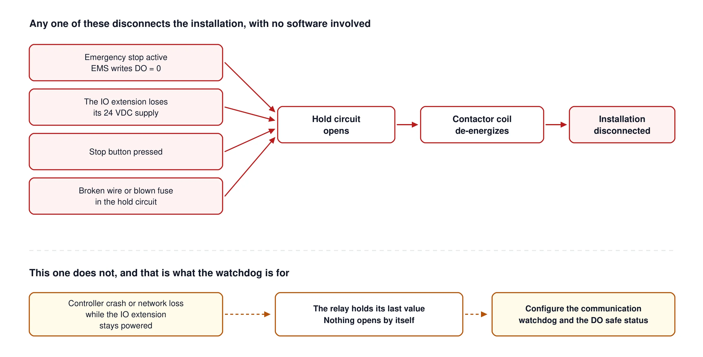
Four independent failures all open the same hold circuit and disconnect the installation, with no software involved. The fifth one does not: with the IO extension powered but unreachable, the relay keeps the last value it was given. That is what the communication watchdog and the per-channel safe status are for.
The IO module must be in managed mode. A module set to unmanaged is only read, never written, so its outputs will not be actuated.
Monitoring and troubleshooting
If a DSO RTU emergency stop is active but the EMS cannot actuate the configured output (for example the module is offline or its relay state cannot be read back), a critical incident is raised. It clears automatically once the module is reachable again and the output is confirmed.
If you see this incident:
- Check network connectivity to the IO module (IP, port, slave ID).
- Verify the module is powered and reachable over Modbus TCP.
- Confirm the module is configured as managed.
Voltmasters tests the hardware emergency stop end to end during commissioning.