DSO RTU
IO module
The IO module: the device that gives the EMS digital inputs and relay outputs, used for hardware emergency stops, grid operator signals and switching controllable loads.
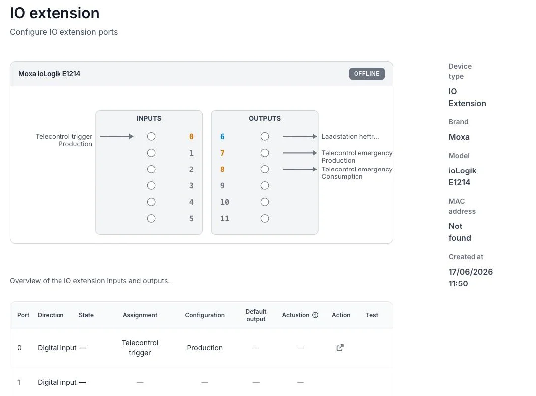
The Ports page of an IO module: inputs on the left, relay outputs on the right, with the function each port carries.
An IO module is a device that gives the Voltmasters EMS a set of digital inputs (DI) and relay outputs (DO) over the installation network. The EMS drives the relay outputs to switch external circuits on or off, and reads the digital inputs to know the position of an external contact.
The relay outputs are used in three ways:
- As a hardware emergency stop for DSO RTU: a relay is wired into the installation's stop circuit and driven when the grid operator triggers an emergency stop. See Emergency stop.
- To switch a controllable load (a simple on/off load such as a heating element or pump) as part of the local control strategy.
- To drive a watchdog back to the grid operator, on links that supervise the connection that way.
On the platform this hardware appears as the device type IO Extension. This section calls the hardware itself the IO module; both refer to the same device.
At a glance
- Channels: 6 digital inputs (DI) and 6 relay outputs (DO) per module.
- Communication: Modbus TCP/IP over the installation network, on a fixed IP address.
- Relay outputs: potential-free, normally-open contacts, wired into the circuit they switch.
- Digital inputs: dry contact or wet contact, read as the position of an external contact: an emergency-stop trigger, or a breaker position reported to the grid operator.
- Power: 24 VDC nominal, DIN-rail mounted.
Check the contact ratings in Technical specifications before wiring anything to a relay output. That page is the single source for what an output may switch directly and when an interposing contactor is required.
For where to place the modules and how many you need, see Placement and cabling.
Adding the IO module on the platform
Add the module like any other device:
- Device type: IO Extension
- Brand: Moxa, Model: ioLogik E1214
- Connection: Modbus TCP/IP, with the module's IP address, port and Modbus slave ID (noted during installation).
The IO module must be in managed mode. A module set to unmanaged is only read, never written, so its relay outputs will not be actuated.
Configuring the ports
Once the device is added, open its Ports page to configure each port. Every port has a direction:
| Direction | Use |
|---|---|
| Digital Input | Read-only. Every input is read and its changes are logged, so the contact position is always visible. The EMS acts on it only where the port is assigned as an emergency stop trigger or to a DSO RTU function (see below); an unassigned input is monitoring only. |
| Relay Output | Switches an external circuit; assign it a function (see below). |
A relay output carries one of two functions:
- Telecontrol emergency stop: the output is driven from a DSO RTU emergency stop. It is assigned in the DSO RTU settings, see Emergency stop; the Ports page shows the assignment and holds the relay actuation mode.
- Controllable load: the output switches an on/off load. See Controllable load.
Outputs that are not assigned remain free for other uses.
Ports assigned from the DSO RTU settings
Some ports are not assigned on this page but in Configuration → Grid & market → DSO RTU settings, because they belong to the grid operator link. Which of them apply depends on the operator; see Grid operators. The Ports page then shows the function the port carries.
Depending on the operator, a port can carry:
- An emergency stop trigger on an input, and the relay outputs that carry out an emergency stop.
- A breaker position the EMS reads and reports to the operator as telemetry, on an input.
- The operator's own watchdog signal, on an input, and the watchdog owed back to the operator, on a relay output.
A relay output driving a watchdog is occupied: it cannot also switch a controllable load, and the platform keeps it out of the load selection.
Manual override
A relay output can be manually overridden to a fixed port state (On or Off), for example during commissioning or maintenance. The override forces the output regardless of the normal control logic; clear it to return the port to automatic control.
Deleting an IO module
An IO module cannot be deleted while its ports are still in use (assigned to an emergency stop or a controllable load). The platform shows which ports are in use and links to the Ports page so you can free them first.
Next steps
- Placement and cabling: how many modules you need and where they go.
- Emergency stop: wire and configure a hardware emergency stop.
- Technical specifications: channels, contact ratings, network, power and environmental limits.
- Controllable load: switch an on/off load through a relay output.